
Hi,
I’m trying to convert my chinese 3040 CNC with VFD spindle to operate from mega. I had a great success by making a proto-shield and outputting signals from mega to internal LPT-ready control board. Now I want to rid of that controller and run everything directly from mega. Trying to use another proto shield and having lots of troubles made me think if there are any mega shields available. Apparently, not. So, I want to try and make one myself.
I guess, my main question would be about optocouplers. While it’s not a problem to find nice little optos for limit switches (817 are generally pretty good and there is a quad versions like LTV-847 available) I’m not so sure about spindle part. I need to turn spindle on/off, switch direction and provide 10v PWM for speed. I have a feeling that even if transistors would work for 10v PWM, it’s better to isolate as much as possible. How would PWM go through an optocoupler; is opto quick enough for the task? Would something like this be good enough for on/off, direction and PWM?
Another thing, should stepper drivers be isolated as well? I mean, generally the drivers have optos on them anyway, but would having an extra be bad and slow everything down?
And lastly, considering that not many pins are really used on mega and the main reason that mega is used is for it’s chip, would a dedicated driver board on 2560 be better than mega+shield?
评论 (10)
#2 – Avalonnw 于 2017-08-06
That’s interesting that in the manual for VFD that I found there is a mention of 0-10, 0-5 and PWM control however I have no idea how… I have attached the manual:
VFD English manual.pdf
Setting D031 has an option 1 – AVI terminal (0-10/0-5v) – the way it’s wired now and option 4 – PWM input which, apparently, refers to MI4 input (in Chinese part of the manual).
To make it more universal, 10v analog converter from mega would be possibly better, though.
#3 – X3msnake 于 2017-08-07
From what i read from the manual You have a 3 state selection switch that
defines how the pwm input behaves. Center is 0-5 full right is 0-10 and
left is outer lead box protection whatever That means
No dia segunda-feira, 7 de agosto de 2017, Anton
escreveu:
> That’s interesting that in the manual for VFD that I found there is a
> mention of 0-10, 0-5 and PWM control however I have no idea how… I have
> attached the manual:
> VFD English manual.pdf
> <https://github.com/gnea/grbl-Mega/files/1203544/VFD.English.manual.pdf>
> Setting D031 has an option 1 – AVI terminal (0-10/0-5v) – the way it’s
> wired now and option 4 – PWM input which, apparently, refers to MI4 input
> (in Chinese part of the manual).
> To make it more universal, 10v analog converter from mega would be
> possibly better, though.
>
> —
> You are receiving this because you are subscribed to this thread.
> Reply to this email directly, view it on GitHub
> <https://github.com/gnea/grbl-Mega/issues/34#issuecomment-320539901>, or mute
> the thread
> <https://github.com/notifications/unsubscribe-auth/AKke-q-Fd7L56h3Mxo9DZkN-z64N39WNks5sVkzHgaJpZM4Ouq3h>
> .
>
—
Com os melhores cumprimentos,
Vinicius Silva
#4 – Avalonnw 于 2017-08-07
@X3msnake the problem is, I can’t find it on the actual VFD ![]()
#5 – csatti 于 2017-08-07
!2017-08-07_113706
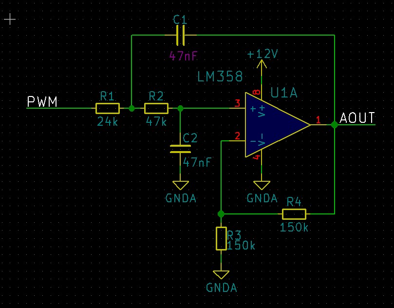
So here is your 2nd order low-pass Butterworth filter, with a 100Hz cutoff frequency and a gain of 2. Make sure that your mega gets 5V or it won’t be able to output the maximum 10V. USB power supplies are often bellow 5V!
#6 – X3msnake 于 2017-08-07
[image: Imagem intercalada 1]
apparently only the 1.5kw has this switch you probabaly have the 0.75kw
2017-08-07 1:37 GMT+01:00 Anton
> @X3msnake <https://github.com/x3msnake> the problem is, I can’t find it
> on the actual VFD ![]()
>
> —
> You are receiving this because you were mentioned.
> Reply to this email directly, view it on GitHub
> <https://github.com/gnea/grbl-Mega/issues/34#issuecomment-320543476>, or mute
> the thread
> <https://github.com/notifications/unsubscribe-auth/AKke-pxOKvRv8h-ZsW5dteNQO8SSPq8Aks5sVlxGgaJpZM4Ouq3h>
> .
>
—
Com os melhores cumprimentos,
Vinicius Silva
#7 – Avalonnw 于 2017-08-08
@csatti thanks for the schematics. Why wouldn’t classic RC filter work? Spindle rpm doesn’t have to react fast to changes, so you can filter hard and get almost no ripple
@X3msnake there are solder pads with labels 0-5v and 0-10v, bat they are weirdly located. Maybe it’s safer to go with whatever set on VFD by default.
Also, my VFD is 1.5kW model.
#8 – X3msnake 于 2017-08-08
Yes better to do that, we don’t know what else is missing in the design,
these boards are usually design with dual model in mind, and usually the
changes have to do do with more than just one component.
Keep us posted ![]()
2017-08-08 2:20 GMT+01:00 Anton
> @csatti <https://github.com/csatti> thanks for the schematics. Why
> wouldn’t classic RC filter work? Spindle rpm doesn’t have to react fast to
> changes, so you can filter hard and get almost no ripple
>
> @X3msnake <https://github.com/x3msnake> there are solder pads with labels
> 0-5v and 0-10v, bat they are weirdly located. Maybe it’s safer to go with
> whatever set on VFD by default.
>
> —
> You are receiving this because you were mentioned.
> Reply to this email directly, view it on GitHub
> <https://github.com/gnea/grbl-Mega/issues/34#issuecomment-320823243>, or mute
> the thread
> <https://github.com/notifications/unsubscribe-auth/AKke-ioj8DEz_xViaehIlv-Nt6Qe7839ks5sV7fugaJpZM4Ouq3h>
> .
>
—
Com os melhores cumprimentos,
Vinicius Silva
#9 – Avalonnw 于 2017-08-08
@csatti Another option would be to have a Arduino Nano (or just a bare atmel) reading PWM and controlling digital pot… Not sure how well that would work though.
#10 – csatti 于 2017-08-09
The opamp’s main function is to levelshift your signal from a maximum of 5V to 10V. This circuit makes it even nicer as it will also filter your PWM signal and the output will be low impedance instead of a high impedance one you would get with a simple RC filter. Filtering too hard would really slow down your spindle reaction and run up time. You would normally want to be able to set the ramp times on your frequency converter instead of having a fixed one made by your circuit.
Using a separate microcontroller and digital pot sounds way too over-complicated to me, especially as you could build up this simple amplifier/filter circuit from some cheap and easy to get parts.
![[gnea/grbl-Mega Issue#1] $ command extentions](https://www.grblhal.com/wp-content/themes/gitphp/timthumb.php?src=https://www.grblhal.com/wp-content/themes/gitphp/assets/img/pic/1.jpg&h=110&w=185&q=90&zc=1&ct=1)
![[gnea/grbl-Mega Issue#2] Better interrupt priorities](https://www.grblhal.com/wp-content/themes/gitphp/timthumb.php?src=https://www.grblhal.com/wp-content/themes/gitphp/assets/img/pic/4.jpg&h=110&w=185&q=90&zc=1&ct=1)
![[gnea/grbl-Mega Issue#3] ATMega16U2 virtual com port on ATMega2560](https://www.grblhal.com/wp-content/themes/gitphp/timthumb.php?src=https://www.grblhal.com/wp-content/themes/gitphp/assets/img/pic/5.jpg&h=110&w=185&q=90&zc=1&ct=1)
#1 – csatti 于 2017-08-06
Hi,
Let’s clarify a few things first. My guess is that your VFD speed control is done via a 0-10V analog signal (I haven’t seen in my life a frequency converter having PWM input). Is that correct? If yes, you have a 5V PWM signal coming from the Mega (I don’t know the frequency but it is important) that needs to be converted to 0-10V analog. You can do it with an opamp in Sallen-Key low-pass filter configuration. If you tell me the frequency, I can give you some component values for the filter.
If the inputs of your stepper drivers are isolated, you should not isolate it yourself. You would need to have an additional isolated power supply and very fast optocouplers for the signals and all for nothing.