
Hi, I must be dense as I have spent most of today searching for pin assignment.
I want to use a Mega+RAMPS-1.4 or one of these, shield as I have them.
I have a laser that takes a 5KHz PWM/TTL signal to drive intensity from 1% to 98% duty cycle.
I cannot find instructions on which pin to use on the Mega (or that shield) as the PWM/TTL output to drive the laser. Is there a “pins.h” I am not seeing?
Could someone please help here as I’d like to use grbl+Mega and LaserWeb.
评论 (10)
#2 – thawkins 于 2019-08-27
Im also looking for this information, i need to know which pins the spindle pwm, and spindle direction data is output from.
A diagram of where each function is located would be cool.
#3 – thawkins 于 2019-09-01
This is an example of a wiring diagram for the grbl-Mega-5X project which is another AtMega/Ramps grbl project, but with 5 Axis support, this level of information is very useful for grtting it up and running. If we could have a simular diagram for the grbl-mega project (it may be very simular)
https://github.com/fra589/grbl-Mega-5X/blob/edge/doc/images/grbl-Mega-5X_Wiring.svg
#4 – bdurbrow 于 2019-09-04
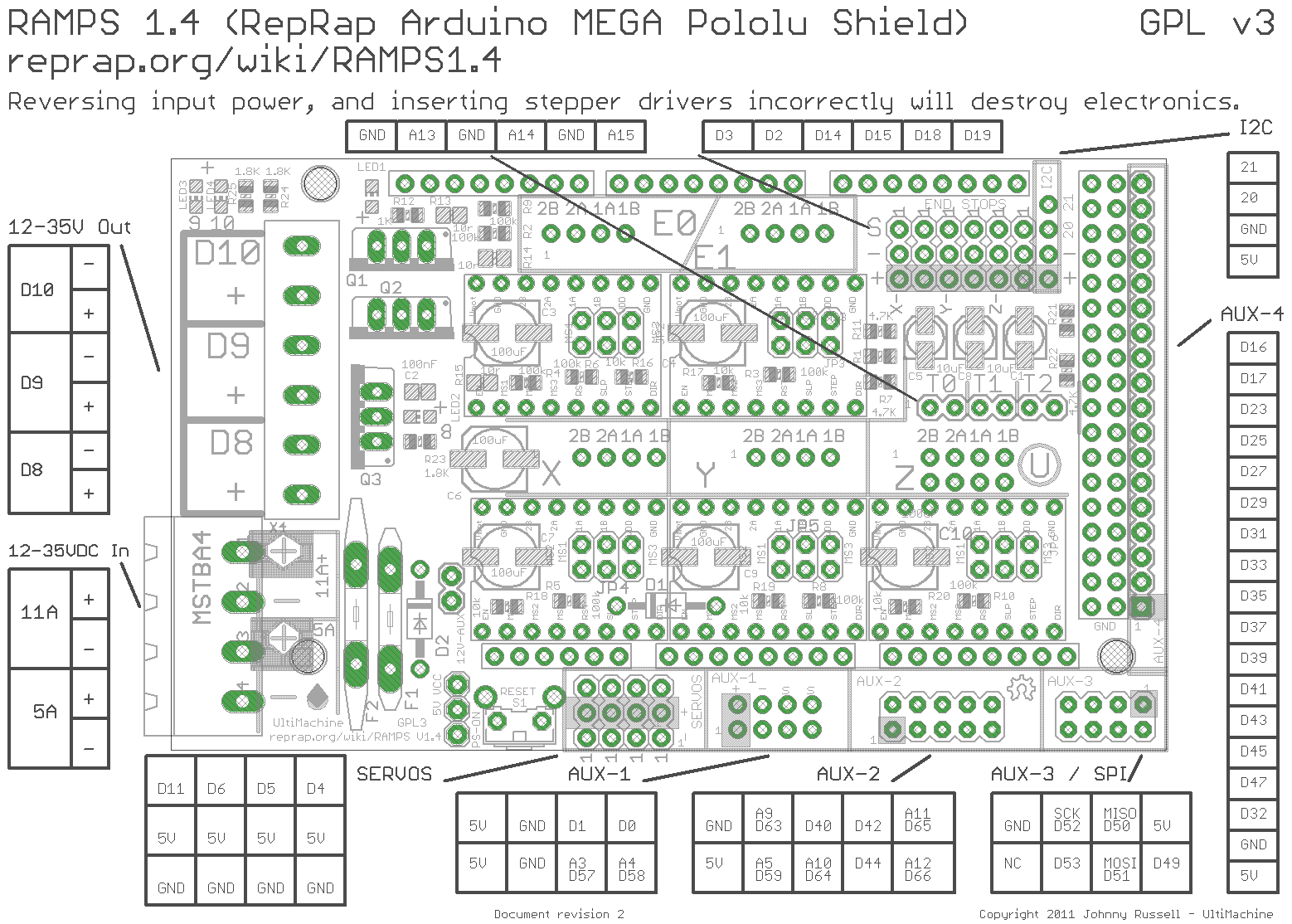
It’s defined in cpu_map.h. Also helpful for figuring out the pinout is the RAMPS connector mapping:
https://reprap.org/mediawiki/images/c/ca/Arduinomega1-4connectors.png
The relevant section of cpu_map.h:
“
  // Define spindle enable and spindle direction output pins.

  #define SPINDLEENABLEDDR      DDRG

  #define SPINDLEENABLEPORT     PORTG

  #define SPINDLEENABLEBIT      5 // MEGA2560 Digital Pin 4 - Ramps 1.4 Servo 4 Signal pin

  #define SPINDLEDIRECTIONDDR   DDRE

  #define SPINDLEDIRECTIONPORT  PORTE

  #define SPINDLEDIRECTIONBIT   3 // MEGA2560 Digital Pin 5 - Ramps 1.4 Servo 3 Signal pin
slightly further down:
`
  // Define spindle output pins.

  #define SPINDLEPWMDDR   DDRH

  #define SPINDLEPWMPORT  PORTH

  #define SPINDLEPWMBIT   5 // MEGA2560 Digital Pin 8
#5 – sanalejo171 于 2019-09-13
Hello, I’ve been 2 days, testing 1 by 1 ALL the ramp pines, I can turn on and off the SPINDLER (DRILL) but none has pwm control, because they only mark 0 or 5v …….. IT ALSO WORKS ME PROBE or analog 15 or none, and probe one by one ……. someone found the solution? Or will I have to go back to Arduino one?
#6 – fra589 于 2019-09-13
Hi,
The default spindle PWM pin defined in cpu_map.h for RAMP board is the D8 pin defined with this :
(only D8 can output PWM more than 5v on RAMP board)
“
  // Define spindle output pins.

  #define SPINDLEPWMDDR   DDRH

  #define SPINDLEPWMPORT  PORTH

  #define SPINDLEPWMBIT   5 // MEGA2560 Digital Pin 8
Then, the PWM output range is defined by this (still in cpu_map.h) :
  // Advanced Configuration Below You should not need to touch these variables

  // Set Timer up to use TIMER4B which is attached to Digital Pin 8 - Ramps 1.4 12v output with heat sink

  #define SPINDLEPWMMAX_VALUE     1024.0 // Translates to about 1.9 kHz PWM frequency at 1/8 prescaler

  #ifndef SPINDLEPWMMIN_VALUE

    #define SPINDLEPWMMIN_VALUE   1   // Must be greater than zero.

  #endif

  #define SPINDLEPWMOFF_VALUE     0

  #define SPINDLEPWMRANGE         (SPINDLEPWMMAXVALUE-SPINDLEPWMMINVALUE)
Then, you need to define MIN and MAX speed in the DEFAULTSRAMPSBOARD section of default.h file :
#ifdef DEFAULTSRAMPSBOARD

  #define DEFAULTSPINDLERPM_MAX 1000.0 // rpm

  #define DEFAULTSPINDLERPM_MIN 0.0 // rpm
(those default values can be adjusted after flashing by the $30 and $30 Grbl parameters).
If your RAMP is 12v powered, the SPINDLEPWMMAXVALUE is 1024 and the SPINDLERPM_MAX is 1000, then the max output of PWM will be 12v when using :
M3 S1000
It will be about 6v using :
You can adjust max power lower than the RAMP input voltage by adjusting the SPINDLEPWMMAX_VALUE lower than 1024.
I hope this help you,
@++;
Gauthier.
#7 – sanalejo171 于 2019-09-13
> Hola,
> el pin PWM de husillo predeterminado definido en cpu_map.h para la placa RAMP es el pin D8 definido con esto:
> (solo D8 puede emitir PWM más de 5v en la placa RAMP)
>
> “
>   // Define spindle output pins.

>   #define SPINDLEPWMDDR   DDRH

>   #define SPINDLEPWMPORT  PORTH

>   #define SPINDLEPWMBIT   5 // MEGA2560 Digital Pin 8

>
>

> Entonces, el rango de salida PWM se define por esto (todavía en cpu_map.h):

>

>
>   // Advanced Configuration Below You should not need to touch these variables

>   // Set Timer up to use TIMER4B which is attached to Digital Pin 8 - Ramps 1.4 12v output with heat sink

>   #define SPINDLEPWMMAX_VALUE     1024.0 // Translates to about 1.9 kHz PWM frequency at 1/8 prescaler

>   #ifndef SPINDLEPWMMIN_VALUE

>     #define SPINDLEPWMMIN_VALUE   1   // Must be greater than zero.

>   #endif

>   #define SPINDLEPWMOFF_VALUE     0

>   #define SPINDLEPWMRANGE         (SPINDLEPWMMAXVALUE-SPINDLEPWMMINVALUE)

>
>

> Luego, debe definir la velocidad MIN y MAX en la sección DEFAULTSRAMPSBOARD del archivo default.h:

>

>
> #ifdef DEFAULTSRAMPSBOARD

>   #define DEFAULTSPINDLERPM_MAX 1000.0 // rpm

>   #define DEFAULTSPINDLERPM_MIN 0.0 // rpm

>
>

> (esos valores predeterminados se pueden ajustar después de parpadear con los parámetros Grbl de $ 30 y $ 30).

>

> Si su RAMP está alimentada por 12v, el SPINDLEPWMMAXVALUE es 1024 y el SPINDLERPM_MAX es 1000, entonces la salida máxima de PWM será de 12v cuando se use:

>
> será de aproximadamente 6v usando:

>
>
> Puede ajustar la potencia máxima más baja que el voltaje de entrada RAMP ajustando el SPINDLEPWMMAX_VALUE más bajo que 1024.
>
> Espero que esto te ayude,
>
> @ ++;
>
> Gauthier
Hi, first thanks for implementing this necessary firmware for ramps and for responding so quickly:
1. The probe did not work in any way, with version 1.1f of your program, I finally found this site where you host the latest versions https://github.com/fra589/grbl-Mega-5X/releases
2. The pwm worked on d8, it was necessary to connect a source of 12 I just made a bridge of the main and perfect source, I am using a mosfet irf 540n, to control a 42v spindle connect + to the gate – to the voltage in and the third leg to the spindle negative and the spindle positive direct to the source everything finally works, I no longer need a shield v3
3. I would like to learn how to edit the code, because in this expression: #define SPINDLEPWMBIT 5 // MEGA2560 Digital Pin 8 ………………. says bit 5 but it works with pin 8, where I know which bit corresponds to which pin ???? thank you
#8 – fra589 于 2019-09-14
Hi,
The v1.1f release on my fra589’s grbl-Mega-5X github is not fully up to date, I wrote some bugs corrections and new enhancements since 2018 july.
I published the hex file coresponding to the latest source release 1.1l.20190605 today.
To modify the cpu_map.h file, you need to know how the port mappingof the microcontroler.
if you see the Arduino’s doc here : https://www.arduino.cc/en/Hacking/PinMapping2560, you can see that the D8 pin is connected on the microcontroler port H at bit 5. so, you need to define :
“
  #define SPINDLEPWMDDR   DDRH

  #define SPINDLEPWMPORT  PORTH
for the port, and :
#define SPINDLEPWMBIT 5
for the bit number on the I/O port.
For more precise niformations on how to programming the microcontroler, you can see ATmega2560 datasheet here :
https://www.microchip.com/wwwproducts/en/ATmega2560
@++;
Gauthier.
#9 – ksdfpr 于 2020-01-21
>
>
> Hi,
> The v1.1f release on my fra589’s grbl-Mega-5X github is not fully up to date, I wrote some bugs corrections and new enhancements since 2018 july.
> I published the hex file coresponding to the latest source release 1.1l.20190605 today.
>
> To modify the cpu_map.h file, you need to know how the port mappingof the microcontroler.
> if you see the Arduino’s doc here : https://www.arduino.cc/en/Hacking/PinMapping2560, you can see that the D8 pin is connected on the microcontroler port H at bit 5. so, you need to define :
>
> “
>   #define SPINDLEPWMDDR   DDRH

>   #define SPINDLEPWMPORT  PORTH

>
>

> for the port, and :

>

>
>   #define SPINDLEPWMBIT   5

>
>
> for the bit number on the I/O port.
>
> For more precise niformations on how to programming the microcontroler, you can see ATmega2560 datasheet here :
> https://www.microchip.com/wwwproducts/en/ATmega2560
>
> @++;
> Gauthier.
Could you help me with this board? (GT2560) What have I to change to work with PWM3 (physical pin 1) bed pin?
Here is the board https://www.geeetech.com/forum/viewtopic.php?t=19092&start=10#p84673
I have made some tests but without pwm success, only on/off.
Laser ttl freq 0-20KHz
#10 – jransp 于 2020-04-07
Ok , PWM TO TTL
It’s very easy just get a PNP transistor and 2 resistors. PWM signal is the spindle negative signal wire
![[gnea/grbl-Mega Issue#1] $ command extentions](https://www.grblhal.com/wp-content/themes/gitphp/timthumb.php?src=https://www.grblhal.com/wp-content/themes/gitphp/assets/img/pic/6.jpg&h=110&w=185&q=90&zc=1&ct=1)
![[gnea/grbl-Mega Issue#2] Better interrupt priorities](https://www.grblhal.com/wp-content/themes/gitphp/timthumb.php?src=https://www.grblhal.com/wp-content/themes/gitphp/assets/img/pic/11.jpg&h=110&w=185&q=90&zc=1&ct=1)
![[gnea/grbl-Mega Issue#4] Real-time adjustable feedrates](https://www.grblhal.com/wp-content/themes/gitphp/timthumb.php?src=https://www.grblhal.com/wp-content/themes/gitphp/assets/img/pic/7.jpg&h=110&w=185&q=90&zc=1&ct=1)
#1 – FlailAway 于 2019-05-27
Anyone here?
The grbl wiki shows “1KHz” as “common” and says to change the cpu_map.h. That file shows 1.9KHz which is closer to 2KHz but no idea how or what to set for 5KHz.