
- This is an example on how to orientate the g-code to fit the object present in the machine.
- For testing I’ve placed at a random position and orientation, a PCB that I made some time ago.
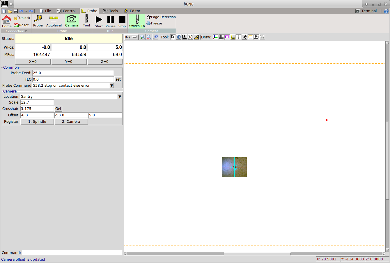
- Switch to the camera system, by clicking the “Switch” button on the ribbon.
The button creats a virtual offset with G92 on the present workspace as the centre is moved
to the camera location. - By switching back to the spindle, the offset is cancelled with a G92.1 command
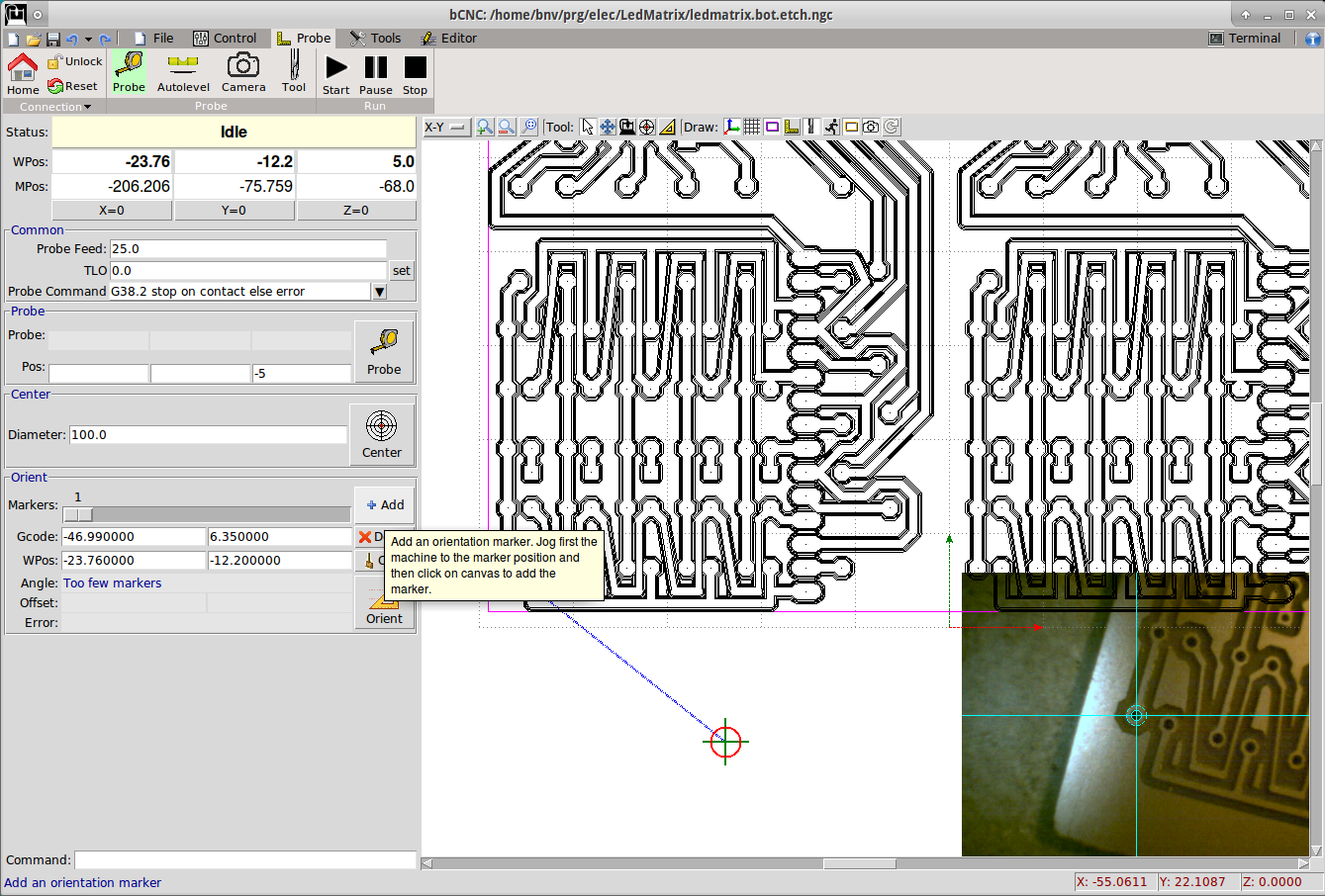
- Change to the “Probe -> Probe” tab
- In the PCB the holes are 0.6mm, so I set the Diameter to 0.6mm
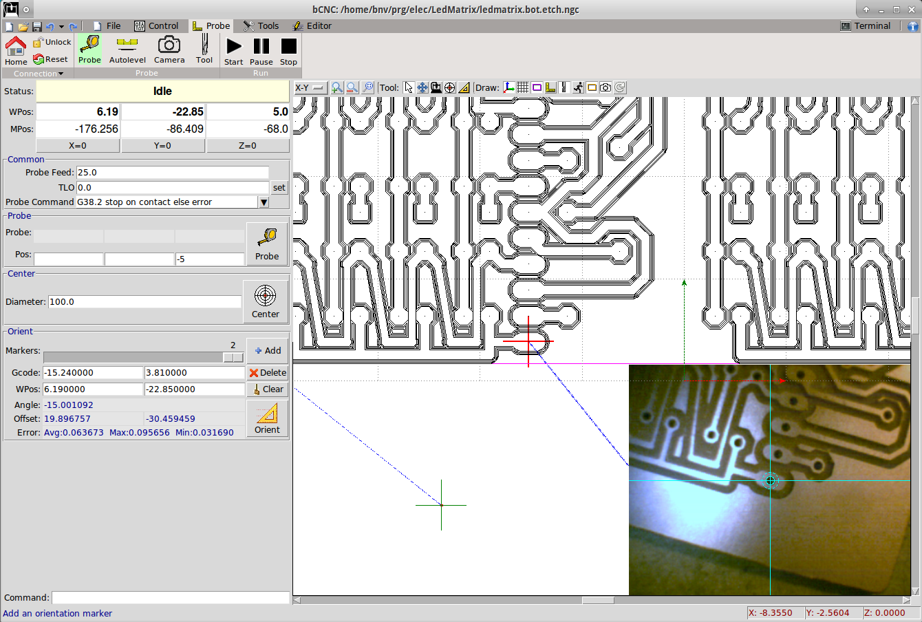
- Jog the camera to a known location. In this example I’ve used a couple of drilled holes.
- Click on the Orient -> Add button
- Click with the mouse to the line on the centre of the hole.
Note: there is a snapping mechanism in bCNC, that will snap to the closest gcode control point
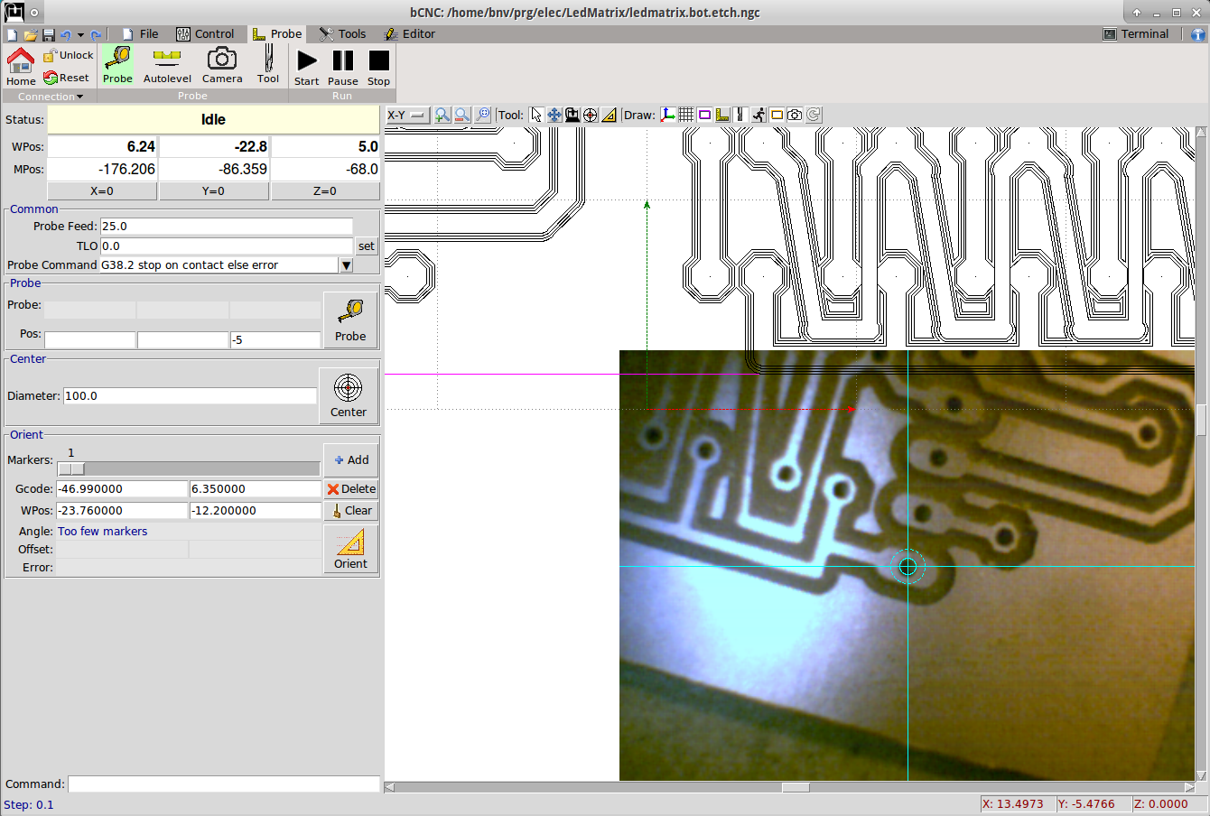
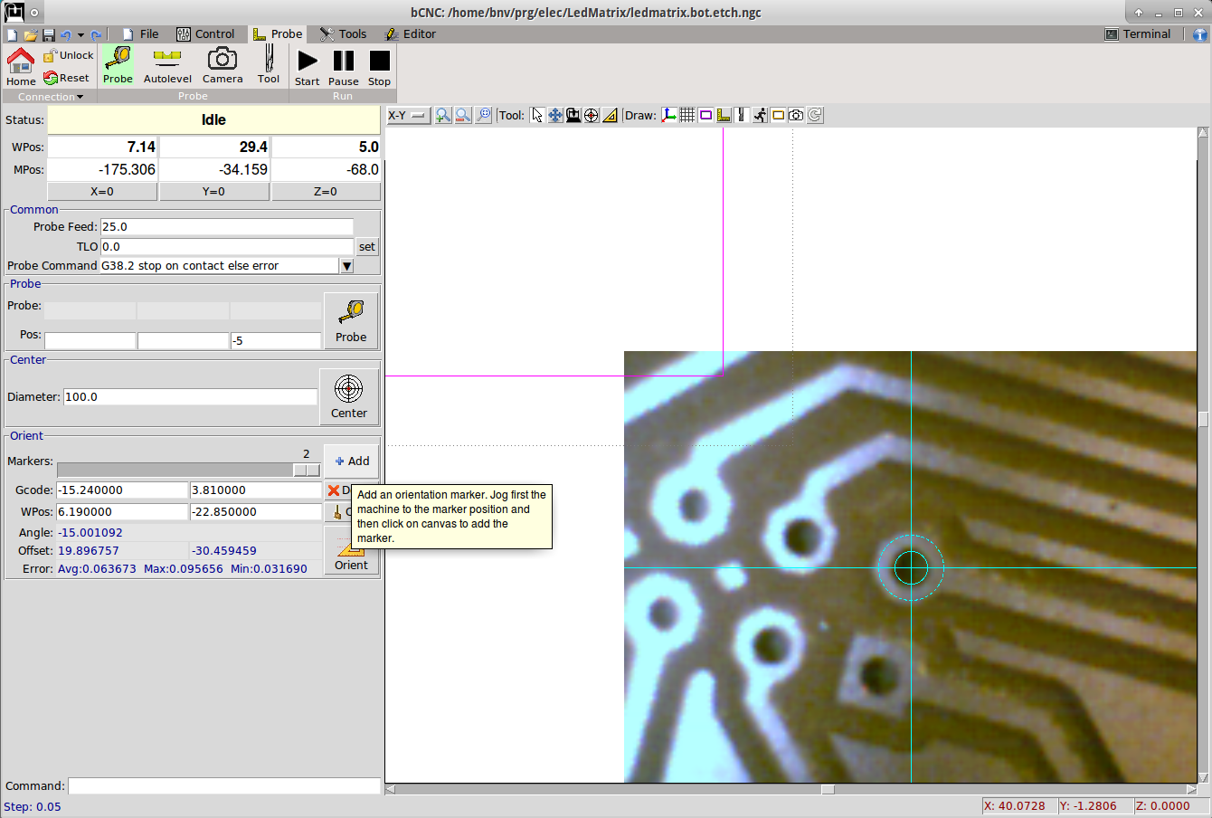
- Jog to the 2nd marker
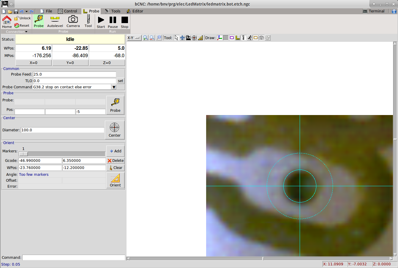
- Zoom and align the camera on the second marker
- In this quick example I had to make steps of 20um to align the holes
- Click on Orient->Add
- Click on the second marker gcode point on the canvas
- Repeat with a 3rd marker
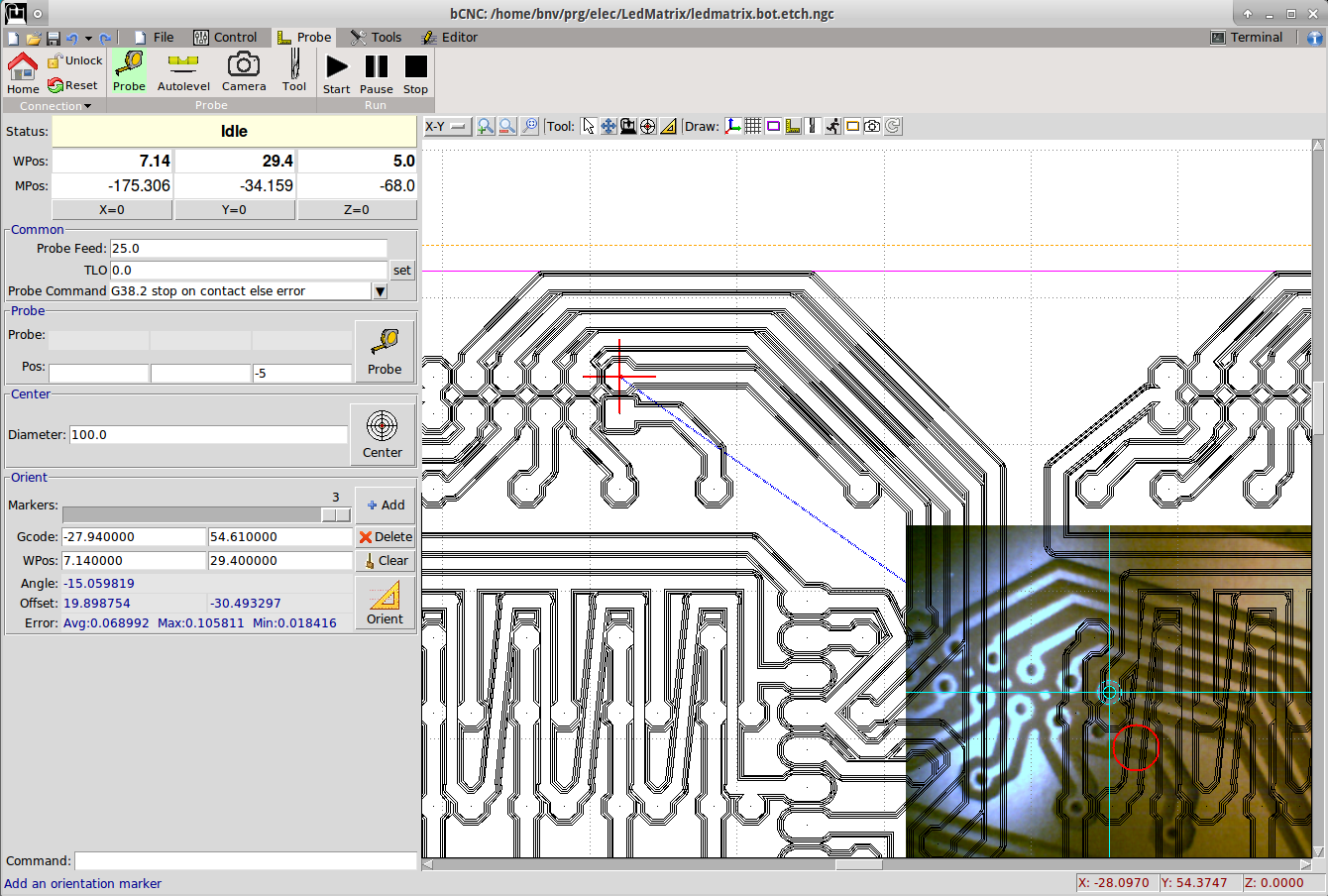
- Add the 3rd marker
- Note: 2 markers are sufficient, but the more you provide the more accurate the system is going to be determined. bCNC is solving an overdetermined system to find the best match.
- Note: always observe the error for each marker. If too high, you can move the marker with the mouse or delete and add again.
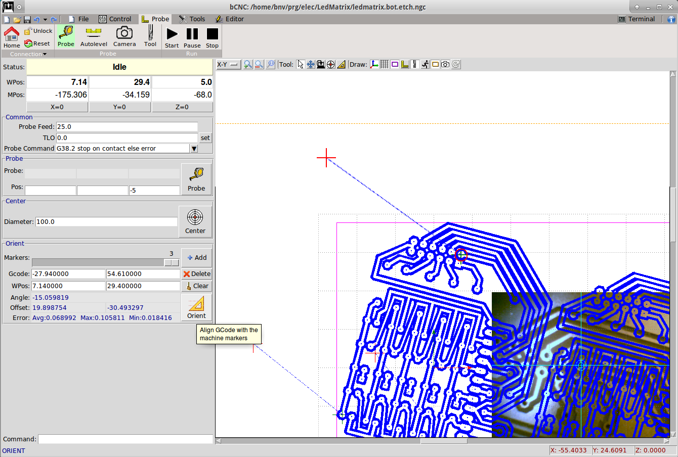
- At this point clicking on the Orient -> Orient button the gcode will be transformed to match the markers.
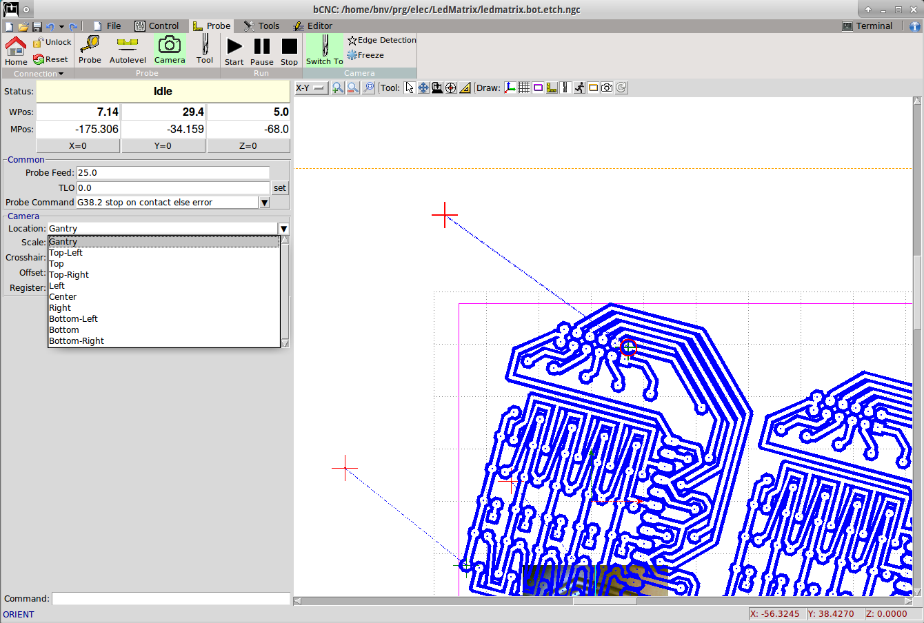
- I’ve changed the location of the Camera display from Bottom Right to Gantry so that the camera image
follows the gantry location when displayed in X-Y
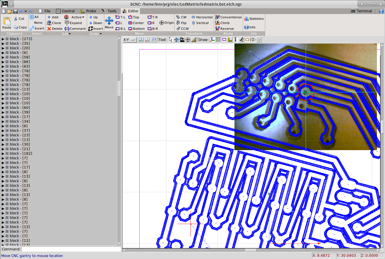
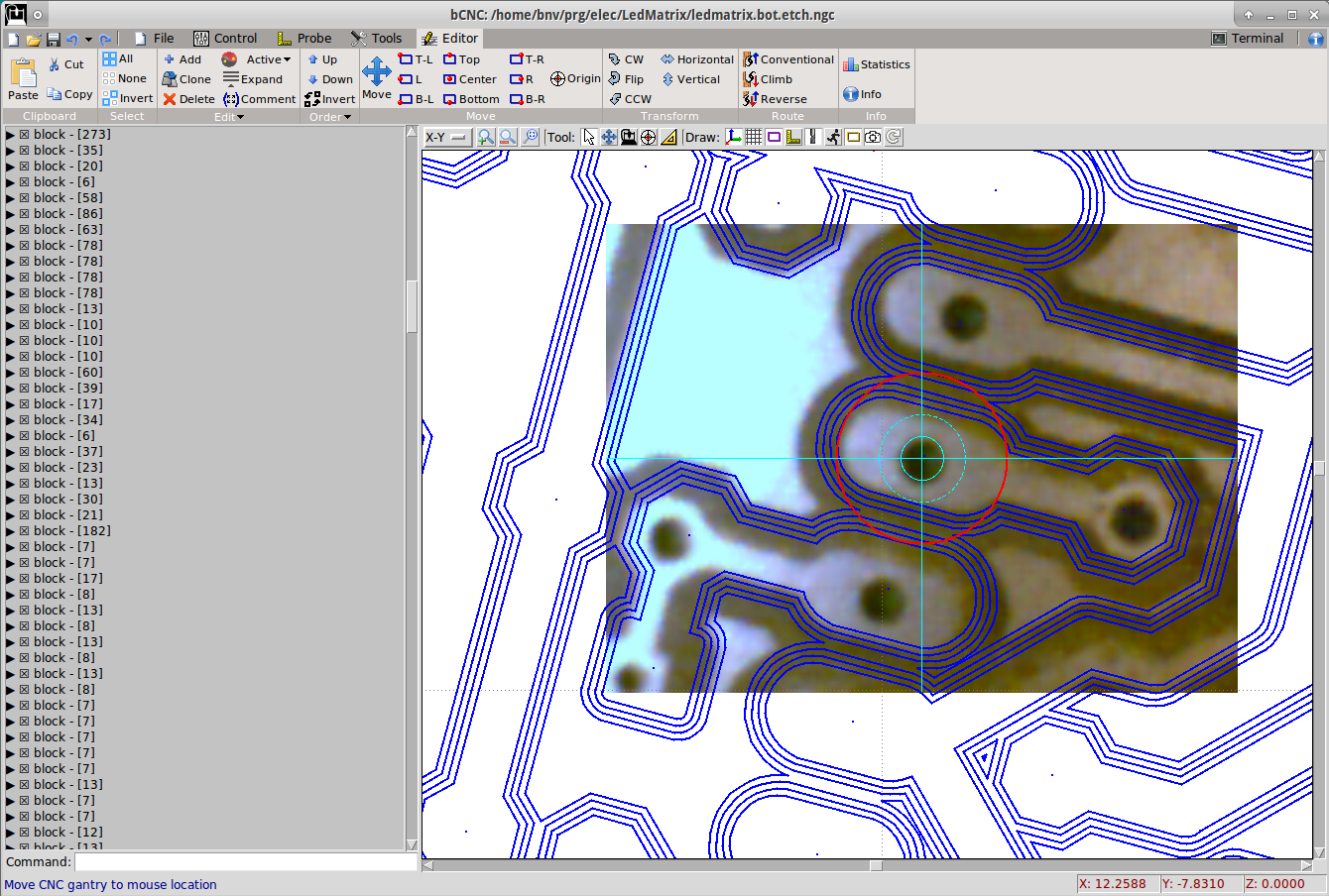
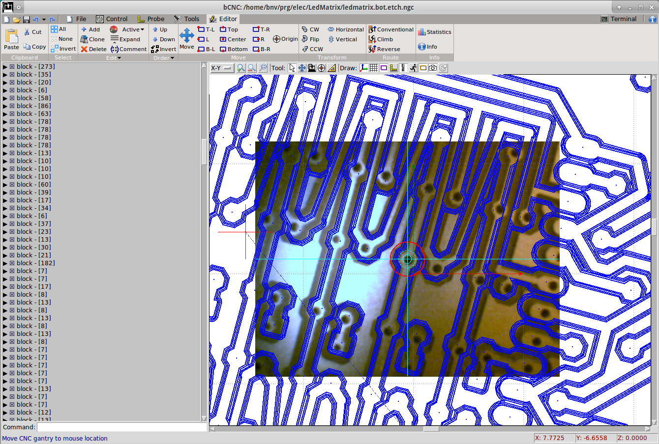
- Inspect some points and see the camera image with the gcode overlay.
-
Note: The image distortion from the macro focusing is visible. The gcode is matching close to the
center but at larger distances is distorted.
本文转载自: https://github.com/vlachoudis/bCNC/wiki/Tutorials:-Orientation-of-gcode
![[gnea/grbl-Mega Issue#1] $ command extentions](https://www.grblhal.com/wp-content/themes/gitphp/timthumb.php?src=https://www.grblhal.com/wp-content/themes/gitphp/assets/img/pic/7.jpg&h=110&w=185&q=90&zc=1&ct=1)
![[gnea/grbl-Mega Issue#2] Better interrupt priorities](https://www.grblhal.com/wp-content/themes/gitphp/timthumb.php?src=https://www.grblhal.com/wp-content/themes/gitphp/assets/img/pic/6.jpg&h=110&w=185&q=90&zc=1&ct=1)
![[gnea/grbl-Mega Issue#4] Real-time adjustable feedrates](https://www.grblhal.com/wp-content/themes/gitphp/timthumb.php?src=https://www.grblhal.com/wp-content/themes/gitphp/assets/img/pic/10.jpg&h=110&w=185&q=90&zc=1&ct=1)