
What version of the firmware are you using?
Ver 1.3a
Is the problem repeatable?
Yes it is repeatable. Leaving the VFD running and performing a ESP32 reset will allow for one single update to the spindle speed before the SetSpeedCommand function wont execute and the update speed packet wont be sent again.
Under what conditions does the bug occur?
The issue is present in the “Test_Drive” machine file with only the H2A spindle enabled.
Couple of points:
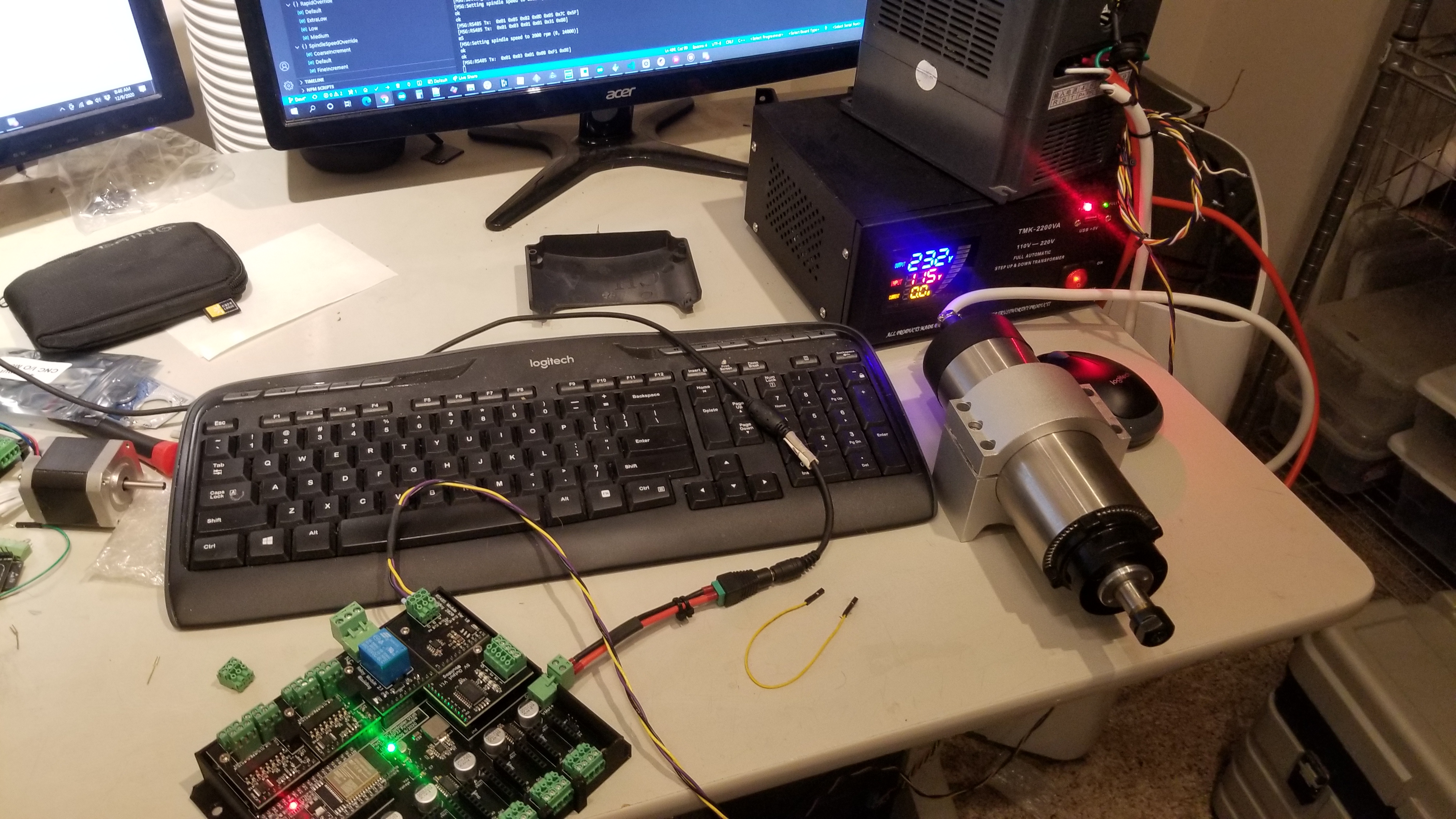
This is using custom hardware where everything seems to work fine from what I can tell. The RS485 commands are being sent correctly and the VFD is responding to them and replying back with the correct values. This leads me to believe that nothing is wrong with the RS485 transmitter side.
Defining the “VFDDEBUGMODE” shows what message are being sent and these match to the data being seen by the bus sniffer seeing. The VFD is responding correctly. However, when viewing the receive packets in the serial terminal, the RX packet shows nothing was received…. strange and yes I have double, tripped, quadruple checked my pins to ensure they’re connected to the correct ones and they are:
“
#define VFDRS485TXDPIN		GPIONUM_17

#define VFDRS485RXDPIN		GPIONUM_16

#define VFDRS485RTSPIN		GPIONUM_4
Remember this is custom hardware so some pins are different to that of the 6-pack.
It gets even more strange as I have seen data in the serial terminal in the past and no hardware changes has been made – so for this reason I don’t want to rule out any issues with the RX side post transceiver side.
Sending M3, M4 commands starts the spindle to the minimum spindle speed in a CC and CCW direction (I think this is a characteristic of my VFD) – no issues here.
Sending “M3 S####” and M4 “S####” (#### is some RPM value) starts the spindle but doesn’t change the speed from the minimum RPM of the VFD drive.
Sending M5 Stops the spindle.
As you can see my problem lies with the speed command.
When I have “VFDDEBUGMODE” disabled and send spindle commands via the terminal, I get a response of “OK” after each command and only some times would I get a message along the lines of “VFD did not respond”. I don’t think I care about a response as long and the spindle drive actions the command (just getting the VFD to go to a specific speed is a big leap for me any way!). I must admit, I lost some faith in the debug mode, are we sure it’s working as expected?
Couple of questions:
1. Does the firmware do anything the with VDF response?
a. If the software doesn’t do anything with the data then I wont worry about figuring out why its not receiving data (I’ve spent three days trying to figure this out and running out of ideas)
2. When does the setspeedcommand run?
a. Should this packet be sent with every “M3 S####” and M4 “S####” Command? (it currently doesn’t).
b. can I force this to be sent again?
3. Is this issue related to the software not seeing a response and not trying to send that type of command again?
Any help is much appreciated!
Kind Regards Pete
评论 (11)
#2 – RootCNC 于 2020-12-06
Sure,
I’ve just downloaded a fresh new clone of the repo and done these changes
1. Change spindle type in the test_drive.h file to:
“
#define SPINDLE_TYPE                    SpindleType::H2A  // only one spindle at a time

#define VFDRS485TXDPIN		GPIONUM_17

#define VFDRS485RXDPIN		GPIONUM_16

#define VFDRS485RTSPIN		GPIONUM_4
2. Uploaded the code

3. Open terminal and start sending M commands.
Notes
This yields and Alarm code 10 error but I don't think this stop the RS845 data from being sent and the data is sent regardless? I believe due to the software not seeing a response it actually sends the command three times. We can capture the output data using the usb to Serial converted to remove any adverse effects from any external factors, such as the VFD drive it self.
Hardware setup
ESP32 on this custom board I mentioned before with the second serial port connected to the RS485 buffer. The buffer is connected to a RS485 to USB serial converter and nothing else. This will mean we won't see a response from the spindle. but I dont think thats going to be an issue - I might be wrong?
Since the last message I have got more confidence that the HW is working and that it is work as expected. The TX and RX is working fine, although the software isn't seeing the response - this might be a bug or something else I've not spotted with the software.
ESP32 GRBL controller -> RS-485 buffer -> cabling -> RS-485 to USB serial adapter.
Testing
- [x] 1. Send "M4" command:
`
0103700C00021EC8
0103700C00021EC8
0103700C00021EC8< polling the modbus
0106200000060208
Works as expected.
- [x] 2. Send "M3" command:
`
0103300000018B0A
0103300000018B0A
0103300000018B0A
0103700C00021EC8
0103700C00021EC8
0103700C00021EC8< polling the modbus
01062000000143CA
Works As expected.
- [x] 3. *Preform reset" Send "M4 S10000" command:
`
0103700C00021EC8
0103700C00021EC8
0103700C00021EC8< polling the modbus
01062000000203CB
0106100027109736
0106100027109736
0103300000018B0A< back to normal polling the modbus
0103300000018B0A
0103300000018B0A
0103700C00021EC8
0103700C00021EC8
etc
Works As expected.
- [ ] 4. NO RESET - Send "M4 S20000" command:
No Write Command for spindle speed observed in terminal
- [ ] 5. Perform reset - Send "M4 S10000" wait a second, send "M4 S20000" wait a second, send "M5"
`
0103700C00021EC8
0103700C00021EC8
0103700C00021EC8< polling the modbus
0106200000060208
0106100027109736
0106100027109736
0103700C00021EC8< back to normal polling the modbus
0103700C00021EC8
0103700C00021EC8
0103300000018B0A
.
.
.
0103700C00021EC8
0103700C00021EC8
0103700C00021EC8
0106200000060208
Odd behaviour - not what I was expecting - I did repeat these steps on multiple times but did not yield the correct answer.
- [ ] 6. Perform reset - Send "M3 S10000" wait a second, send "M3 S20000" wait a second, send "M5"
`
0103300000018B0A
0103300000018B0A
0103300000018B0A
01062000000143CA
0106100027109736
0106100027109736
0103700C00021EC8
0103700C00021EC8
0103700C00021EC8
.
.
.
0103300000018B0A
0103700C00021EC8
0103700C00021EC8
0103700C00021EC8
0106200000060208
This highlights the spindle command from the serial terminal does not actually send the updated speed command on the modbus.
- [ ] 7. Perform reset - Send "M3 S10000" wait a second, send "M4 S20000" wait a second, send "M5"
`
0103700C00021EC8
0103300000018B0A
0103300000018B0A
0103300000018B0A
01062000000143CA
0106100027109736
0106100027109736
0103700C00021EC8
0103700C00021EC8
.
.
.
0103700C00021EC8
0103700C00021EC8
01062000000203CB
The direction commands seem to be sent correctly - but the speed command doesn't follow after the first speed command.
- [ ] 8. Perform reset - Send "M3 S10000" wait a second, send "M5" wait a second, send "M3 S20000" wait a second, send "M5"
`
0103700C00021EC8
0103700C00021EC8
01062000000143CA
0106100027109736
0106100027109736
0103300000018B0A
0103300000018B0A
.
.
.
0103300000018B0A
0103700C00021EC8
0103700C00021EC8
0103700C00021EC8
0106200000060208
Conclusion
From tests 4,6,7,8 it would seem sending a spindle command with an updated speed for the second in the serial terminal, will not actually send the updated speed set point to the spindle controller. Only upon reset can the spindle speed be set. I would have expected the spindle "M3/4 S####" to send the speed set point the VFD controller regardless of the previous state?
I did have a play around with the HUANYANG spindle too and this shows the same effect, so maybe there's some else at play?
Could this be an attribute of the software not seeing a response from the spindle? Does the ESP32 have to see a response?
I hope this help convey the issue, if not - please let me know.
I've had a peak into the code but this way past my skill set! I don't mind getting my hands dirty but I wouldn't know were to start!
Thanks again Bart.
#3 - RootCNC 于 2020-12-06
PS sorry for the long post!
#4 - bdring 于 2020-12-06
I'll read that when I get some time. If you rewrite it as below, I might be able to get to it sooner.
gcode sent --- expected behavior --- actual behavior (be brief)
Note: I only have a Huanyang spindle.
#5 - RootCNC 于 2020-12-07
I'll test the Huanyang spindle type out tomorrow - I believe this exhibits the same issue
#6 - RootCNC 于 2020-12-07
Testing the Huanyang spindle type, as per the previous setup:
- [X] 1. Perform reset of GRBL and send "M3".
Code Sent:
M3
Expected:
01 03 01 01 + CRC
Got:
010301013188
Working as expected
- [x] 2. NO reset to GRBL send "M5".
Code Sent:
M5
Expected:
01 03 01 08 + CRC
Got:
01030108F18E
Working as expected
- [x] 3. NO reset to GRBL send "M4".
Code Sent:
M4
Expected:
01 03 01 11 + CRC
Got:
010301113044
Working as expected
- [x] 4. No reset to GRBL send "M3 S2000".
Code Sent:
M3 S2000
Expected:
``
01 05 02 ## ## + CRC

01 03 01 01 + CRC
Value dependant on the S### portion of the Gcode - we're not interested in the value, just that this line is sent

Got:
01050206823B0D

010301013188
Working as expected - This was the first time sending a spindle command with a speed parameter. this has been noted to work fine for the first run but not for subsequent commands with the spindle speed parameter.
- [ ] 5. No reset to GRBL send "M3 S4000".
Code Sent:
M3 S2000
Expected:
01 05 02 ## ## + CRC
Value dependant on the S### portion of the Gcode - we're not interested in the value, just that this line is sent

Got:

Error - No change in spindle speed observed in RS485 serial data.
This identifies the issues of only a single spindle speed command being sent once GRBL boots up. I would expect the spindle speed to be updated with that of the new spindle speed set point of 4000RPM.
- [ ] 6. No reset to GRBL send "M5" and then "M3 S6000" (new spindle setpoint).
Code Sent:
`
M5

M3 S6000
Expected:
01 03 01 08 + CRC

01 05 02 ## ## + CRC

01 03 01 01 + CRC
Got:
01030108F18E

010301013188
Error - Again no spindle setpoint was sent over the Modbus, I might be getting confused but I am expecting the spindle speed command to be sent when the spindle command with a S parameter to update the VFD?
Unless I'm missing something, this is identifying there is a common issues between the two spindle types.
Kind Regards Pete
#7 - KingMo5h 于 2020-12-08
I think you have the same problem as him: https://github.com/bdring/Grbl_Esp32/issues/689
#8 - scottbez1 于 2020-12-09
Can you share what the debug lines say when you issue your S#### command, with VFDDEBUGMODE enabled?
It will look something like [MSG:Setting spindle speed to 10000 rpm (8000, 24000)]
Looking at the code, the most obvious reason I see that a speed command would not be sent is if the (bounded) RPM is the same as the most recently set (bounded) RPM -- in other words, even if you command 2 different speeds via g-code, if those speeds are both outside the bounds of the defined min/max RPM configured in your grbl settings then the bounds checks would force them to the same value and it would be expected for the second speed command to not be sent at all. It would be helpful to rule out this possibility before digging further.
If that is not what's happening here, I think it could be helpful if you could include the actual full RX/TX data from one of the failing test cases (i.e. without removing the specific speed values or CRC values) along with the rest of the VFDDEBUGMODE messages, so it's easier to check the data against the expected protocol in case that gives any additional clues as to what might be happening. I was not able to reproduce this on my (Huanyang) machine, even if I occasionally detached the RO pin on the RS485 transceiver at various times, so any additional clues or data you can provide would be helpful.
#9 - bdring 于 2020-12-09
I finally got a chance to test this. It is a pain because I need to move it to my office, and I don't have the right voltage.
The VFD RS485 class is a basic implementation, but I think it executes your test from a performance standpoint.
Here is my setup...
VFD PD011 is 120 // min RPM
Boot messages
[MSG:Initializing RS485 VFD spindle]
[MSG:VFD RS485 Tx:GPIO(14) Rx:GPIO(15) RTS:GPIO(13)]
Relevant Grbl settings are...
$Spindle/Enable/OffWithSpeed=On

$GCode/MaxS=24000.000

$Spindle/Delay/SpinDown=8.000

$Spindle/Delay/SpinUp=8.000
$Spindle/Type=HUANYANG
Here is a sequence of commands
M3 ;enters M3 with no speed
ok
$G ; show gcode modes
[GC:G0 G54 G17 G21 G90 G94 M3 M9 T0 F0 S0]
ok
M5 ; enters M5 mode
ok
$G
[GC:G0 G54 G17 G21 G90 G94 M5 M9 T0 F0 S0]
M4 ; enter M4 mode no speed
ok
$G
[GC:G0 G54 G17 G21 G90 G94 M4 M9 T0 F0 S0]
ok
M3S2000 ; M3 spindle spins in correct direction
ok
$G
[GC:G0 G54 G17 G21 G90 G94 M3 M9 T0 F0 S2000]
We welcome any improvements and pull requests, but it takes a few days to setup and test. Some devs do not have the capability to test. It is very expensive to keep this equipment around just for testing.
#10 - RootCNC 于 2020-12-09
@bdring @scottbez1
Well.... I feel like a numpty. The golden bullet was the $GCode/MaxS=24000.000 command to set the spindle max point. Once you said it, it sounded so obvious! Thank you for your help! I cannot protary how happy I am to finally have the spindle control working on this CNC controller! I really mean it - so happy.
I think I managed to delve too deep into commissioning this new hardware and missed some of the simple stuff off, with being new to GRBL and all that (I'm coming across from Marlin so some methods of configuration are done differently - im still learning)
Solution:
I think we can close this issue and anyone reading this thread should ensure the following settings have been set for the control of ANY VFD:
``
$Spindle/Enable/OffWithSpeed=On
$GCode/MaxS=24000.000
$Spindle/Delay/SpinDown=8.000
$Spindle/Delay/SpinUp=8.000
Side note - @bdring I can see the RX message is not being displayed in your terminal? I don't see a response either in my terminal with the #define VFDDEBUGMODE` set. All I see is an empty RX message. Now, because I've got the spindle control working, I'm happy to leave it there but I am guessing I should see the returned RS485 message in the terminal window? I did probe the pad of EPS32 and the RX message is definitely getting there... so I'm none the wiser atm. Does the GRBL firmware use the status of VFD? or does it just keep the watchdog happy on the VFD?
Again thank you for your help and this great project - I cannot wait to do more stuff with it.
#11 - bdring 于 2020-12-09
I'll look into the debug mode.
![[gnea/grbl-Mega Issue#1] $ command extentions](https://www.grblhal.com/wp-content/themes/gitphp/timthumb.php?src=https://www.grblhal.com/wp-content/themes/gitphp/assets/img/pic/8.jpg&h=110&w=185&q=90&zc=1&ct=1)
![[gnea/grbl-Mega Issue#2] Better interrupt priorities](https://www.grblhal.com/wp-content/themes/gitphp/timthumb.php?src=https://www.grblhal.com/wp-content/themes/gitphp/assets/img/pic/5.jpg&h=110&w=185&q=90&zc=1&ct=1)
![[gnea/grbl-Mega Issue#3] ATMega16U2 virtual com port on ATMega2560](https://www.grblhal.com/wp-content/themes/gitphp/timthumb.php?src=https://www.grblhal.com/wp-content/themes/gitphp/assets/img/pic/9.jpg&h=110&w=185&q=90&zc=1&ct=1)
#1 – bdring 于 2020-12-05
Can you provide a repeatable, detailed and minimum example of how to create the problem from power on to the problem?
Thank you