
Hello all!
I am new in the forum so I don’t know if here is the correct place to do that or if I can do that, but I did my version from the board ESP32 CNC Controller V3.1, I changed and fixed some pins as I though that is better for my needs and also change some components to buy from the same supplier ( Board – JLCPCB and Components – LCSC). I stop following the forum for a while and now I realize that the software and also the board change a lot, I think that the board actually is V4.1 .
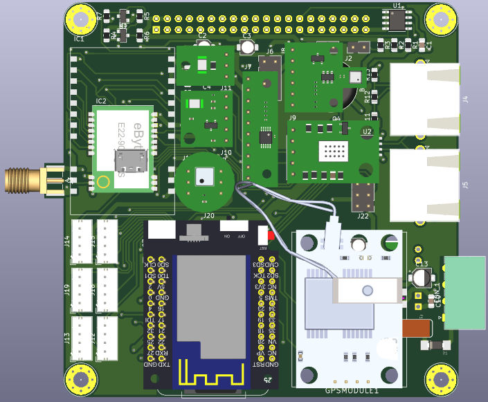
By the way, I’d like your opinion about my Schema and also Board design, I send this to be produced and I will assemble and test it as soom it arrive. I hope that it work.
Here is the schematic and a 3d model picture.
kicad ESP32 CNC-V4 – Schematic.pdf
!TOP
I did the tracks in the board to work at 5 Amps and choose one Step down converter to work at 45V – 3A.
Step down converter TD1509P5: https://lcsc.com/product-detail/DC-DC-ConvertersTechcode-Semicon-TD1509P5C97262.html
The idea for use this current is because Pololu have one step motor driver that have max current per phase 4,5A. I think that with this driver is possible use bigger step motors.
Pololu driver TB67S249FTG Stepper Motor Driver Compact Carrier https://www.pololu.com/product/3096
If is possible also can you help me with the pins map in the file cpu_map.h. I had a lot of questions before, now it is bigger so I’m a bit confused.
I choose the version V3p5 to configure, I will use only one pin for coolant MIST and FLOOD, negative and positive Normally Open limits switch for all axis, spindle direction and SD_card detection.
Choose the version of the board to better Pins configurations:
Line 73 – //#define CPUMAPV3p5 // version 3.5 and earlier to #define CPUMAPV3p5 // version 3.5 and earlier
Line 74 – #define CPUMAPV4 // version 4 or higher (in developement) to //#define CPUMAPV4 // version 4 or higher (in developement)
Coolant configuration:
Line 96 – //#define COOLANTFLOODPIN GPIONUM16 to #define COOLANTFLOODPIN GPIONUM16
Line 116 – //#define COOLANTMISTPIN GPIONUM21 to //#define COOLANTMISTPIN GPIONUM16
Limits axis switch configuration:
If I’m not wrong the old version of cpu_map.h had a way to configure the software to work with positive and negative limits switch, but I didn’t find this in the actual file. Is possible use negative and positive switch in the machine?
To change the switch from NC to NO I need just change the mask, is it correct?
Line 127 – #define LIMITMASK B111 to #define LIMITMASK B000
SPINDLE_DIR configuration:
I didn’t find any configuration for spindle direction and I don’t know what is the function to USERDIGITALPIN_1. Is possible use this to control the spindle direction, the software give conditions to do that?
Line 117 – #define USERDIGITALPIN1 GPIONUM21 to //#define SPINDLEDIRPIN GPIONUM_21
– There is no //#define SPINDLEDIRPIN GPIONUM21, it is just one example for possible variable.
SD_CARD configuration:
I fixed the pins for the SD card, But I don’t know how can I read that (I need learn program yet). If I understood correct the files, actually the software read SD card and use GPIOs 5, 18, 19 and 23, but I don’t know each pin is used as SD Card detect, I choose GPIO 35. It will work or there ins’t pin for that in the software?
Line131 – #define CONTROLSAFETYDOORPIN GPIONUM35 // needs external pullup to //#define SDCARDDETECTPIN GPIONUM35 // needs external pullup
– Also there is no //#define SDCARDDETECTPIN GPIONUM_35 // needs external pullup, it is just one example for possible variable.
These are what I think that is necessary change in the file, I didn’t find any thing more, but I am not sure if these are correct or possible to change.
Thanks,
Antonio.
评论 (3)
#2 – Antonio-Albano 于 2020-01-21
Hello Bdring,
Thanks for the answer.
I will do these modifications in the next version for the board.
About the tracks for 5A I express my self wrong this is just for the Vmot not for the Buck power, buck power is just 3A (normal track).
!Captura de Tela 2020-01-21 às 12 29 43
I will test and learn how to use the firmware and the web interface with this board and im parallel a make a new version.
After I assemble the board, I send a picture.
Thanks again.
#3 – M10CUBE 于 2021-10-24
Hi @Antonio-Albano . I sow your design and it is similar to my M10CUBE dimension. Is it possible to share the KICAD files so to move the design into M10CUBE concept ? (90x90mm with Raspberry 40pin connector)
https://hackaday.io/project/171770-m10cube
Thanks a lot
!M10SE01-01
![[gnea/grbl-Mega Issue#1] $ command extentions](https://www.grblhal.com/wp-content/themes/gitphp/timthumb.php?src=https://www.grblhal.com/wp-content/themes/gitphp/assets/img/pic/5.jpg&h=110&w=185&q=90&zc=1&ct=1)
![[gnea/grbl-Mega Issue#2] Better interrupt priorities](https://www.grblhal.com/wp-content/themes/gitphp/timthumb.php?src=https://www.grblhal.com/wp-content/themes/gitphp/assets/img/pic/4.jpg&h=110&w=185&q=90&zc=1&ct=1)
![[gnea/grbl-Mega Issue#3] ATMega16U2 virtual com port on ATMega2560](https://www.grblhal.com/wp-content/themes/gitphp/timthumb.php?src=https://www.grblhal.com/wp-content/themes/gitphp/assets/img/pic/8.jpg&h=110&w=185&q=90&zc=1&ct=1)
#1 – bdring 于 2020-01-20
I suggest changing it to the V4.1 pinout. Many subtle issues caused the changes from V3.5. This wiki page has a lot of useful info
Here are some suggestions.
1. Change GPIO2 to an output. Many dev boards put an LED on this pin that causes problems for some people as an input. I like to put spindle on it because you can see the speed of the spindle as brightness.
2. Change GPIO15 to an output. It has some pulse at at boot, so I worry about a closed input during boot damaging the circuit.
3. SD Detect is not currently supported in firmware.
4. Your Buck power supply is fine, but you don’t need much 5V current. The 4.5A for the pololus is VMOT