
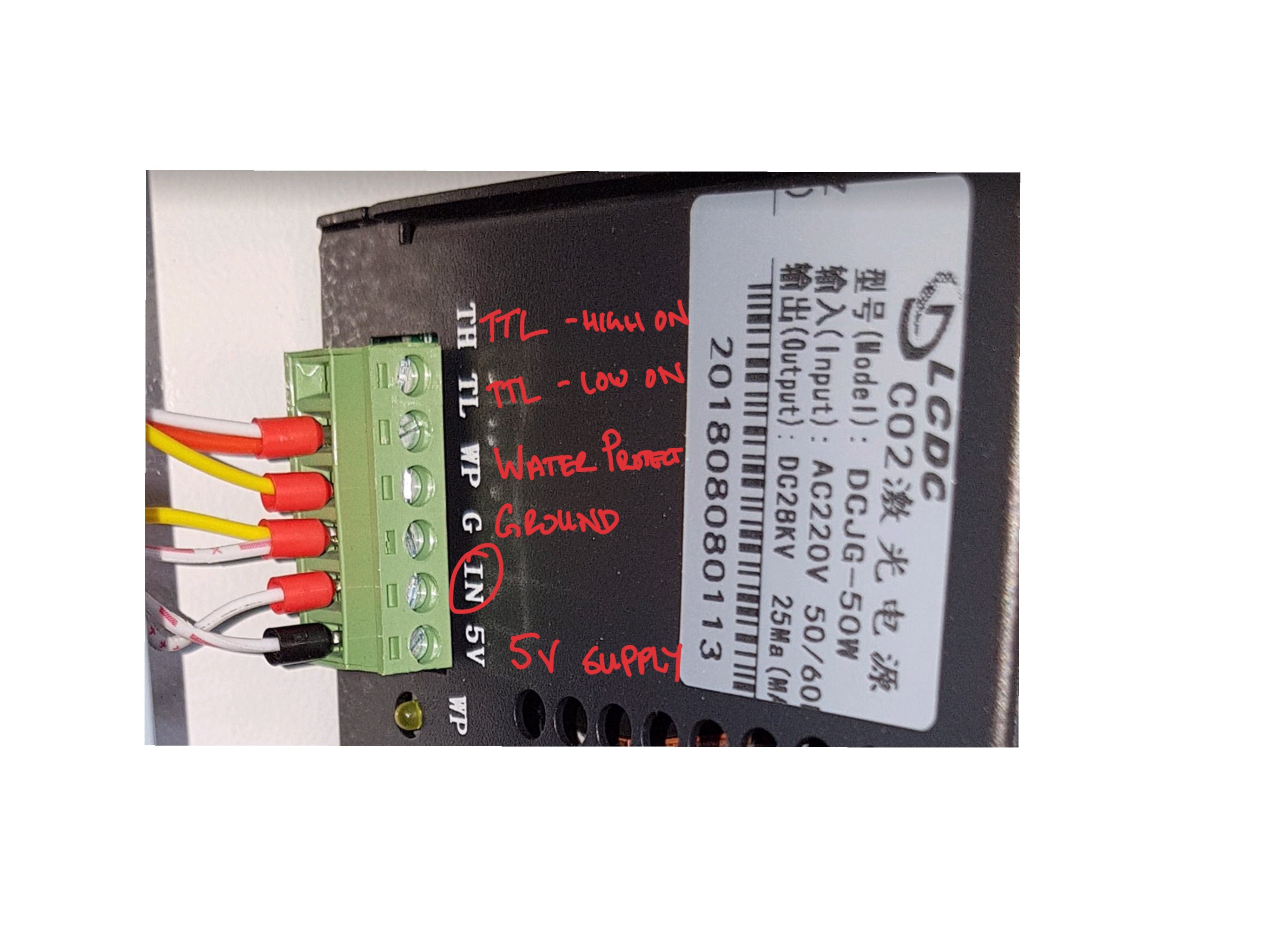
Hi, I have one of your 2.5D boards. I’m not sure how I should connect it to my laser PSU.
I think that the 5v PWM (yellow below) —> “IN” pin
I need another pin for the laser enable (TL or TH).
Maybe I can remap the servo PWM?
or maybe the FET ground pin with a pull-up resistor to the 5v?
Or short the TL to ground and rely only on the laser PWM?
Image of PSU
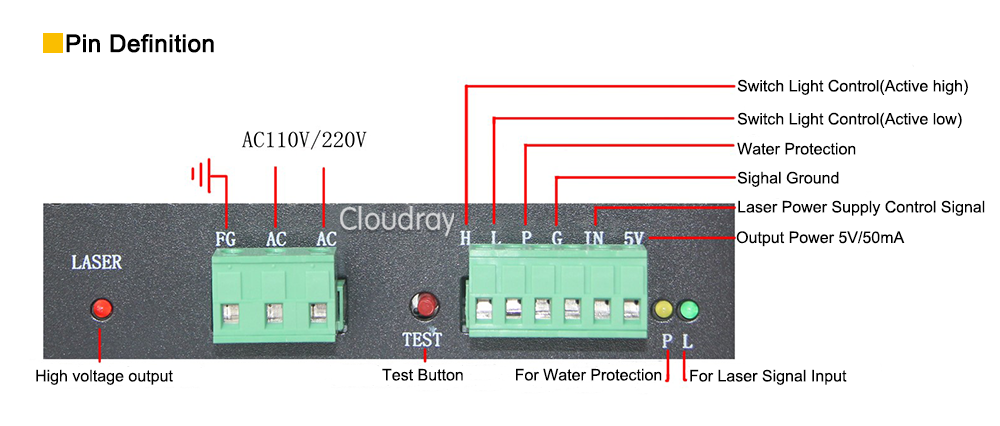
Pin out from similar model
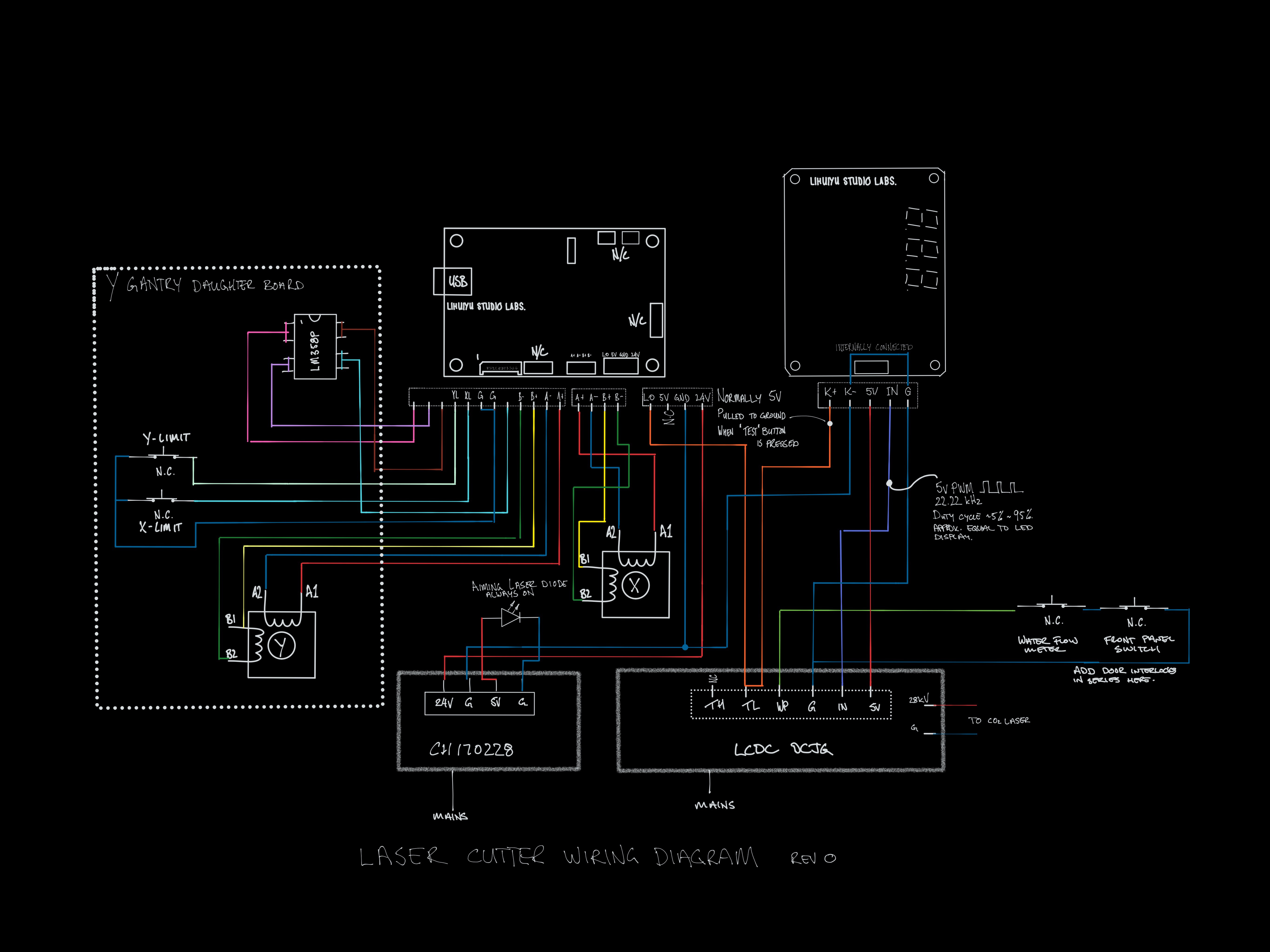
Circuit diagram
2.5D laser controller

评论 (10)
#2 – misan 于 2019-09-28
I would rather use a bipolar transistor.
#3 – brakthehun 于 2019-10-04
I typically connect to the TTL H and I set up my manual fire button from TTL L to ground.
#4 – kjjordans 于 2019-10-13
Hi Bart,
I have a level shifter to convert to 5v, how do I set the servo PWM pin to the Spindle/laser enable in the CPU map? I can’t find the option.
Also, is the dynamic laser power from gbrl1.1 implemented in this branch?
#5 – bdring 于 2019-10-13
The spindle (laser) pin is on GPIONUM17 the servo is on GPIONUM27. The Laser Pwr PWM pin should work as defined. If you want to use the servo PWM pin rather than the Laser Pwr PWM, you would comment out #define USINGSERVO and change #define SPINDLEPWMPIN GPIONUM17 to #define SPINDLEPWMPIN GPIONUM_27
Dynamic Laser Power is implemented. You need to turn it on with $32=1
#6 – kjjordans 于 2019-10-14
Sorry, I was a bit vague.
I would like to keep the laser PWM as is. I want to change the servo PWM to laser/spindle enable and connect it to TH on the PSU. I think that is the correct way to connect this PSU.
Otherwise, I could short TL to ground (or TH to 5v) to make the laser fire with only the PWM signal.
I don’t know if having the enable pin gives any better functionality or safety over relying on the PWM signal
Do you think that there is any need to use the enable pin
#7 – bdring 于 2019-10-14
You can try it. Define a spindle enable pin and assign it pin 27. You only need to change the cpu map file.
#8 – kjjordans 于 2019-10-14
So
#define SPINDLEENABLEPIN GPIONUM27
in the CPU map?
#9 – bdring 于 2019-10-14
Yes, comment out any other uses of GPIONUM27. Commenting out this should do it.
“C++“
//#define USING_SERVO // uncomment to use this feature
#10 – kjjordans 于 2019-11-25
Hi,
I have got everything working. I am using the servo PWM which is 5v for the laser PWM and i am using the laser power PWM pin with a level shifter for laser enable.
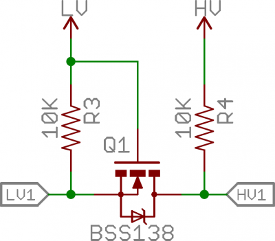
the level shifter is similar to this one. (thanks sparkfun)
!image
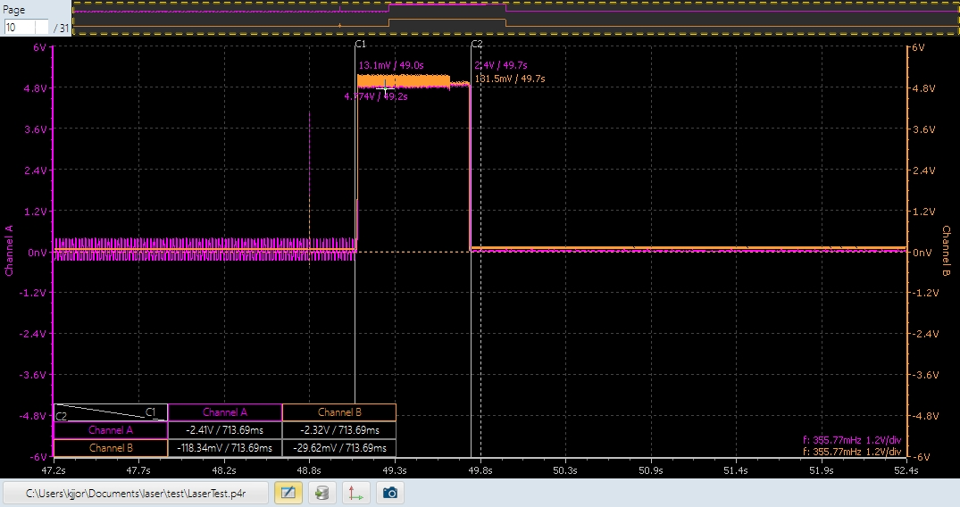
The only problem that i have now is a small spike at startup and reset that is causing the laser to fire.
Any ideas on the best way to stop this? I thought of inverting the enable pin and attach to TL, that way I would need a high signal on the PWM and a low signal on the Enable which i think is unlikely to happen accidentally. What do you think?
!image
notice the small spike as i turn the power on and the long spike during start up. the same signal happens when i restart, only a bit longer.
![[gnea/grbl-Mega Issue#1] $ command extentions](https://www.grblhal.com/wp-content/themes/gitphp/timthumb.php?src=https://www.grblhal.com/wp-content/themes/gitphp/assets/img/pic/7.jpg&h=110&w=185&q=90&zc=1&ct=1)
![[gnea/grbl-Mega Issue#2] Better interrupt priorities](https://www.grblhal.com/wp-content/themes/gitphp/timthumb.php?src=https://www.grblhal.com/wp-content/themes/gitphp/assets/img/pic/12.jpg&h=110&w=185&q=90&zc=1&ct=1)
![[gnea/grbl-Mega Issue#3] ATMega16U2 virtual com port on ATMega2560](https://www.grblhal.com/wp-content/themes/gitphp/timthumb.php?src=https://www.grblhal.com/wp-content/themes/gitphp/assets/img/pic/11.jpg&h=110&w=185&q=90&zc=1&ct=1)
![[gnea/grbl-Mega Issue#4] Real-time adjustable feedrates](https://www.grblhal.com/wp-content/themes/gitphp/timthumb.php?src=https://www.grblhal.com/wp-content/themes/gitphp/assets/img/pic/8.jpg&h=110&w=185&q=90&zc=1&ct=1)
#1 – bdring 于 2019-09-28
The laser PWM pin was intended for laser power control of small lasers. I have tried it on some blue diode laser modules. The signal is only 3.3v, so some laser power supplies may have issues with that.
You idea with the FET and a pull-up might work too.
You can map virtually any function to the laser PWM and Servo PWM pins in the cpu_map.
Be careful. That is a dangerous power supply and laser.