
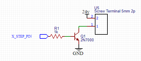
To drive the step and directions I have opted to do this below.
!image
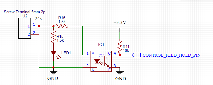
To read the input I am doing this below.
!image
Please make me some suggestions if I am designing a good enough pcb.
评论 (16)
#2 – mac7988 于 2019-09-12
@buildlog
Thank you for the suggestion on the output. I am driving a stepper driver which has a opto in the driver.
input does have have the opto powered it’s a NC state it NO’s when pushbutton is pressed.
#3 – bdring 于 2019-09-12
Does it short 24v to ground in closed state?
#4 – mac7988 于 2019-09-12
yes it shorts to ground.
#5 – mac7988 于 2019-09-12
sorry, I mean total opposite to what I said. It’s a push button that is a NO state depressed and limit sensors are connected NC.
#6 – karoria 于 2019-09-12
I would suggest to tune the value of resistors by seeing the output waveform in DSO. I had a bad experience in stepping up the 3.3v to 24v for pulse signals of motor drives. Your output waveform will distort heavily in most of the cases. Most of the times not giving full 24v output as its peak is shaped like triangle and it goes merely half up. I have already given up of doing step up for my drives and using the pulse signals as is 3.3v. Best of luck for your endeavour. And please share the results here so that I can also come to know my mistakes.
#7 – bdring 于 2019-09-12
Isn’t shorting your 24V to ground a bad thing? That will take down the entire 24V system.
#8 – karoria 于 2019-09-13
I agree with Barton. There must be a resistor in between. And as I said above, you have to try with and find out the optimum resistor value for correct pulse generation. This is the game of response time of semiconductor devices vs pulse frequency. I hope i am able to explain you.
#9 – karoria 于 2019-09-13
And yes, when you tune your circuit, tune it for maximum velocity of your axis. I mean the highest frequency pulse train you are using. And without seeing the signal in DSO, it is quite not possible as inspite your circuit is theoretically right, it may not give the results.
#10 – mac7988 于 2019-09-13
@bart, I see my mistake with the input circuit. You are right it will short the entire system. How do I know? It did short the entire system.😑😒
Lucky it’s only a breadboard trial.
@karoria I will change my step output voltage to 5 volts. My reason to move to 24volt is the ability to use industrial limit sensor for accuracy and reliability.
#11 – karoria 于 2019-09-13
Oh. That is the exact case of mine. I want to share you my experience that most of the inductive type limit sensors work perfectly with 5v !!!! However they mention 12v-24v operating range. I have tried with 2 different manufacturer and both of them worked nicely at 5v. So my suggestion is to buy one such sensor and test it. Yes, i have also noted that they dont work on 3.3v. FYI.
#12 – karoria 于 2019-09-13
So, I take 5v as input to limit sensor and the output signal from it which is also 5v has to be dropped down to less than 3.3v by using resistor so that it can not damage esp32. Value of resistor will depend on the operating current of your sensor.
#13 – mac7988 于 2019-09-13
@karoria if I use a optocoupler than I don’t have to work a out it as there is no electrical connection.
#14 – karoria 于 2019-09-14
I tried all the way. The problem with opto is response time and so the distorted waveform again. But i am not discouraging you as in my case also correct resistors given at least more than 18v step pulse though not 24v. With wrong resistor value you can end up with merely 5v to 8v signal. You have to watch output in DSO to understand what I mean.
As I already told, if your only concern is to take input from industrial sensor, go for it with 5v circuit. I have got consistent results so I recommend that way.
#15 – mac7988 于 2019-09-14
Hi Ravi,
Please check the current setup. I don’t have a opto on the output so I
don’t have an issue here.
On Sat, Sep 14, 2019, 3:49 AM Ravi Karoria
> I tried all the way. The problem with opto is response time and so the
> distorted waveform again. But i am not discouraging you as in my case also
> correct resistors given at least more than 18v step pulse though not 24v.
> With wrong resistor value you can end up with merely 5v to 8v signal. You
> have to watch output in DSO to understand what I mean.
> As I already told, if your only concern is to take input from industrial
> sensor, go for it with 5v circuit. I have got consistent results so I
> recommend that way.
>
> —
> You are receiving this because you authored the thread.
> Reply to this email directly, view it on GitHub
> <https://github.com/bdring/GrblEsp32/issues/217?emailsource=notifications&email_token=AET6ZCOY4VU3LPNIT4KANDTQJSJPHA5CNFSM4IV3ZQDKYY3PNVWWK3TUL52HS4DFVREXG43VMVBW63LNMVXHJKTDN5WW2ZLOORPWSZGOD6WWXPI#issuecomment-531459005>,
> or mute the thread
> <https://github.com/notifications/unsubscribe-auth/AET6ZCMNWCA5DEPUMAHNUQLQJSJPHANCNFSM4IV3ZQDA>
> .
>
#16 – karoria 于 2019-09-14
Give it a try on a breadboard first. You need to attach a resistor before ground. This way you will get non-inverting pulse at collector output.
![[gnea/grbl-Mega Issue#1] $ command extentions](https://www.grblhal.com/wp-content/themes/gitphp/timthumb.php?src=https://www.grblhal.com/wp-content/themes/gitphp/assets/img/pic/11.jpg&h=110&w=185&q=90&zc=1&ct=1)
![[gnea/grbl-Mega Issue#2] Better interrupt priorities](https://www.grblhal.com/wp-content/themes/gitphp/timthumb.php?src=https://www.grblhal.com/wp-content/themes/gitphp/assets/img/pic/7.jpg&h=110&w=185&q=90&zc=1&ct=1)
![[gnea/grbl-Mega Issue#3] ATMega16U2 virtual com port on ATMega2560](https://www.grblhal.com/wp-content/themes/gitphp/timthumb.php?src=https://www.grblhal.com/wp-content/themes/gitphp/assets/img/pic/3.jpg&h=110&w=185&q=90&zc=1&ct=1)
#1 – bdring 于 2019-09-12
I am not an electrical engineer. I have not looked at the datasheets. I am only only looking at your schematic as generic symbols.
Output: It looks OK. What are you driving? If it is an opto on a stepper driver you probably need a current limiting resistor at 24V
Input. It looks like the opto is always powered from the 24V.