
I am working on a test PCB for some upcoming features.
Features working on…
1. SPI drivers in daisy chain mode. This means only one CS is need for all drivers.
2. Diag pins are routed back to ESP32 for stall detection.
3. Optionally use SPI stepper enable rather than wired pins.
4. (4) independant axes. I’ll probably update the code for up to (6)
5. Larger caps (330uF 50V) for high current TMC5160 drivers.
This is just a test bed for trying out new features that may or may not make it into the master branch.
评论 (30)
#2 – bdring 于 2019-06-23
I will be ordering about 10 raw boards and a solder stencil later today. The controller will not work until the firmware changes are done.
The most important change is the SPI cascade mode. This requires the TMCStepper Library to add that feature. There is an issue open on that. There is no timeline for that, so I may need to temporarily just send raw bytes to the SPI rather than the much more friendly and readable library.
The extra axes need to be added to Grbl_ESP32. I have done that on other Grbl ports, so it should not be much of a challenge. I will have an option where two of the axes can be ganged/squared so ShapeOko/X-Carve style machines can benefit.
Edit: The design is open source and I will create a GitHub repo for it soon.
#3 – AbySet 于 2019-06-23
Thank you so much, i will be waiting for them (firmware and GitHub reposity).
#4 – bdring 于 2019-07-03
I got some basic daisy chained SPI drivers features working. I only have two of the TMC5160 drivers. I just hacked the TMCStepper Library a little to make it work. Right now it just sends the same config to all drivers.
#5 – AbySet 于 2019-07-03
WoW, i’m so exited right now, my machine still waiting for that.
Please let me know when all is ready to go, i think i will engrave the pcb with cnc or probably just use the old method (chimical).
I have no words to thank you for all the efforts.
Once my machine is ready i will daily used it and it will be a permanent test for this project.
Thank you so much.
#6 – MtripleM 于 2019-07-05
> I am working on a test PCB for some upcoming features.
>
> !image
>
> Features working on…
>
> 1. SPI drivers in daisy chain mode. This means only one CS is need for all drivers.
> 2. Diag pins are routed back to ESP32 for stall detection.
> 3. Optionally use SPI stepper enable rather than wired pins.
> 4. (4) independant axes. I’ll probably update the code for up to (6)
> 5. Larger caps (330uF 50V) for high current TMC5160 drivers.
>
> This is just a test bed for trying out new features that may or may not make it into the master branch.
How many maximum axis for ESP32 ?
#7 – bdring 于 2019-07-05
I have had Grbl running up to 6 on a different port.
The current Grbl_ESP32 is limited to 3, but I will add 3 more soon.
#8 – shawe 于 2019-07-14
Only to my knowledge, at this time this PCB+ESP32 is similar to this other alternative https://reprap.org/wiki/MiniRambo ?
And in other hand, the increase in CPU power ESP32 vs Arduino, it implies in a fastest work?
#9 – misan 于 2019-07-15
While both boards can control several stepper motors with software to
decode g-code the two boards are not related anyway. Not only they have
different processors (8-bit miniRambo vs 32-bit ESP32 ) and vast
differences in RAM and Flash, but miniRambo is aimed at 3D printers and
PCB+ESP32 is aimed at CNC machines up to 4-axis and/or laser
engraver/cutter.
Or course, a faster processor means the pulse max frequency can be much
higher.
On Mon, Jul 15, 2019 at 12:08 AM Francesc Pineda Segarra < notifications@github.com> wrote:
> Only to my knowledge, at this time this PCB+ESP32 is similar to this other
> alternative https://reprap.org/wiki/MiniRambo ?
>
> And in other hand, the increase in CPU power ESP32 vs Arduino, it implies
> in a fastest work?
>
> —
> You are receiving this because you are subscribed to this thread.
> Reply to this email directly, view it on GitHub
> <https://github.com/bdring/GrblEsp32/issues/171?emailsource=notifications&email_token=AADRZSFTMJF5ULL55TIXRRLP7OPVJA5CNFSM4H2R5Y2KYY3PNVWWK3TUL52HS4DFVREXG43VMVBW63LNMVXHJKTDN5WW2ZLOORPWSZGODZ4OJKA#issuecomment-511239336>,
> or mute the thread
> <https://github.com/notifications/unsubscribe-auth/AADRZSE4PMPX3ALVGMFSWLDP7OPVJANCNFSM4H2R5Y2A>
> .
>
#10 – bdring 于 2019-07-15
The ESP32 was selected for this project primarily for the Bluetooth and WiFi features, but it has proven to be excellent in other areas.
– Very Fast. This can generate high step rates. Steppers can only go so fast before they are useless, but servo motors can use the higher rates. The speed and dual cores also allows background operations, like web server, kinematics, etc to operate without affect on the motion quality.
– RAM The ATMega chips are severally limited.
– Peripherals . The RMT, high speed/resolution PWMs, timers, DACs, UARTs, etc are great and have super flexible pin mapping.
-Cheap and Modular. The small and cheap dev modules are great.
#11 – shawe 于 2019-07-19
@misan @bdring thank for your replies.
I have an ESP32 also, but from Espressif and pin connections are a little different (some extra pins), but it isn’t really a problem.
#12 – JackHouseLab 于 2019-08-18
Hi!
I hope it is right place for my post ![]() (don’t see email or private message for autor of Grbl_ESP32).
(don’t see email or private message for autor of Grbl_ESP32).
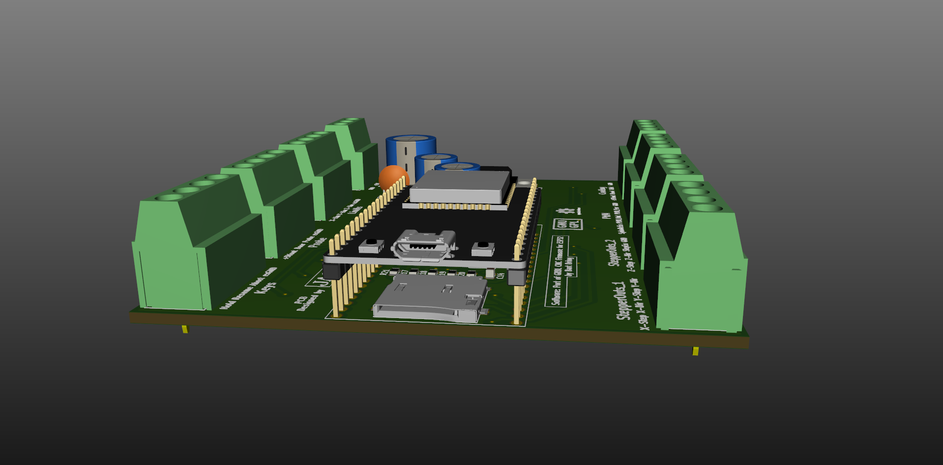
I have designed another version of PCB for GRBL ESP32 project – this time it uses optocouplers on inputs, and pnp transistors on outputs. It is intended to use with external stepper motor drivers like DM5042 or simillar which have optocouplers on its (STEP, DIR ENABLE) inputs.
PCB will be placed in Gainta D6MG enclosure with screw terminal connectors to easy connect to external devices.
This project use ESP32DEVKITC32D version of Espressif module.
Here is some views of this project:
!Grbl_ESP32
!GrblESP32bottom
!GrblESP32enclosure
Project is made in Kicad and Freecad, and is of course intended to be available for people as Open Hardware Project.
It uses current version of software and have functionality limited to this version (3 axes only – there is no more pins on ESP32 to make additional axes without adding more IC’s – like I2C expanders or something like that).
First PCB’s will be ordered (probably) tomorrow – just a few for testing.
I can send project files to author – to make them available for people (for adding to project as alternative or something) if he wants and is planning such cooperation – of course ![]()
This PCB project needs some testing in real word of course – for now it is just virtual project.
Best Regards
#13 – misan 于 2019-08-18
@JackHouseLab I guess you already answered this when you mentioned no more pins left, but a chance to keep an SD card in the board, even if pins were shared with a second function might come in handy.
At any rate, a very nice addition for the larger CNC machines.
#14 – JackHouseLab 于 2019-08-18
A propos SD card….It is hiding under ESP32 module (still exist) ![]()
!GrblESP32SD_view
Some of pins are less useful – like “door”, flood”, “mist” – they may (probably) be reprogrammed and used as 4th-axe.
Don’t know if output signals on STEP pins are realised only by software or use some internal hardware, and any pin may be used to this task. There is about 100kHz on step pins.
#15 – misan 于 2019-08-19
> A propos SD card….It is hiding under ESP32 module (still exist) ![]()
@JackHouseLab That is great then.
#16 – stanw 于 2019-08-20
It looks like you have driver transistors on the step and dir lines. Do they pull up or down? If they pull down, a nearby +5V port will be handy to keep the wiring and loop area minimized to reduce noise and interference.
Looks good.
Stan
> On Aug 18, 2019, at 11:56 PM, Miguel Sanchez
>
> A propos SD card….It is hiding under ESP32 module (still exist) ![]()
>
> @JackHouseLab <https://github.com/JackHouseLab> That is great then.
>
> —
> You are receiving this because you are subscribed to this thread.
> Reply to this email directly, view it on GitHub <https://github.com/bdring/GrblEsp32/issues/171?emailsource=notifications&email_token=AANMXVGEKOGOFCAHPPDSWH3QFI72XA5CNFSM4H2R5Y2KYY3PNVWWK3TUL52HS4DFVREXG43VMVBW63LNMVXHJKTDN5WW2ZLOORPWSZGOD4R4PLI#issuecomment-522438573>, or mute the thread <https://github.com/notifications/unsubscribe-auth/AANMXVBZW3WY442TE6GRIMLQFI72XANCNFSM4H2R5Y2A>.
>
#17 – JackHouseLab 于 2019-08-20
Yes – driver transistors pulls down. You can take +5V from 7805 located in the PCB (or external power supply) and use it to drive optocouplers or relays, etc…
#19 – JackHouseLab 于 2019-08-21
Hi,
I ordered a few PCBs from my local PCB manufacturer, as a part of bigger order – it will be ready for about 3 weeks. Then I will assembly one, and check if everything works correctly.
If yes, I will publish gerber files to community.
I’m not planning to sell boards – you may order PCBs from your local manufacturer, or maybe someone near you do it, and sell to other people…and maybe there is another way….
I prefer designing than selling ![]()
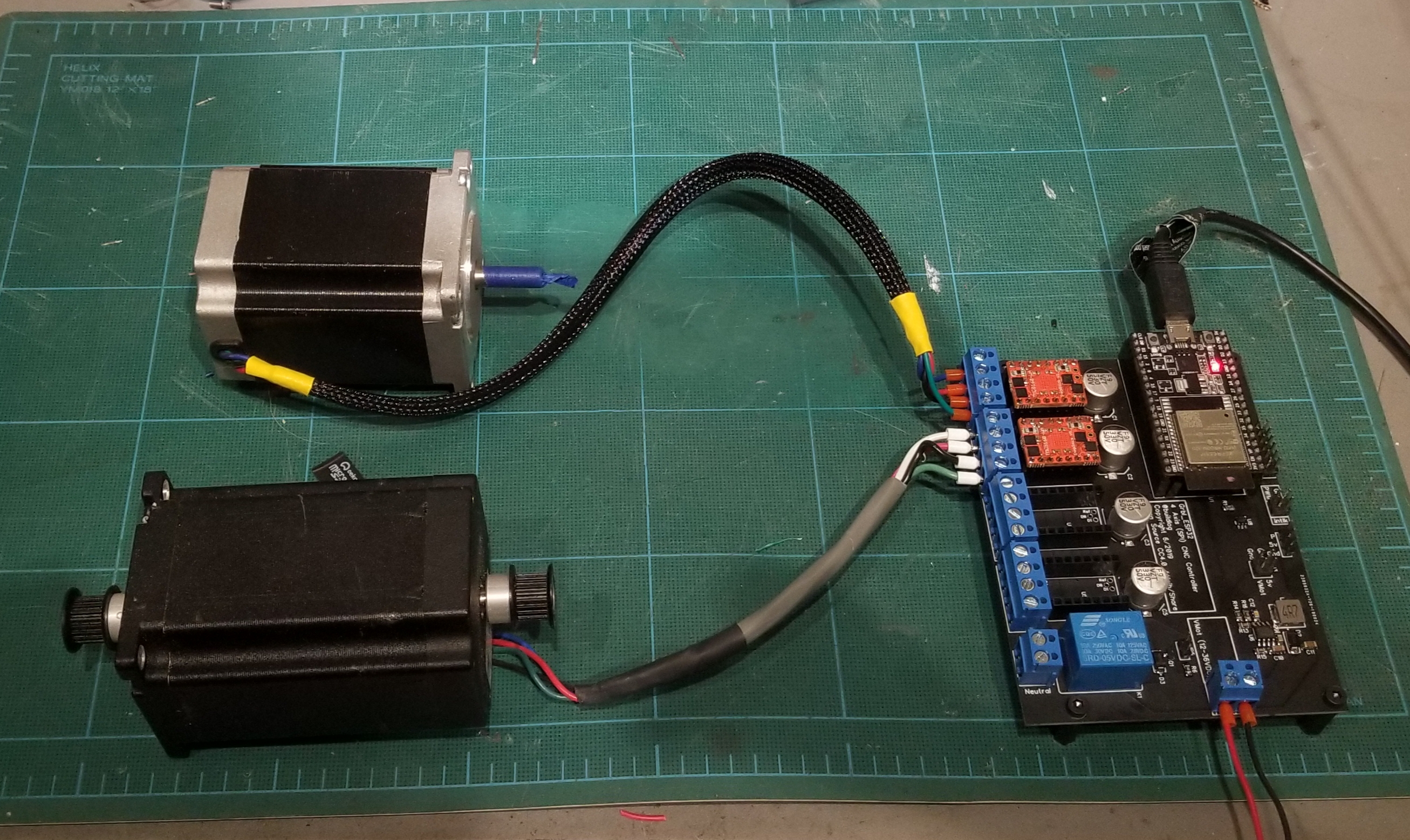
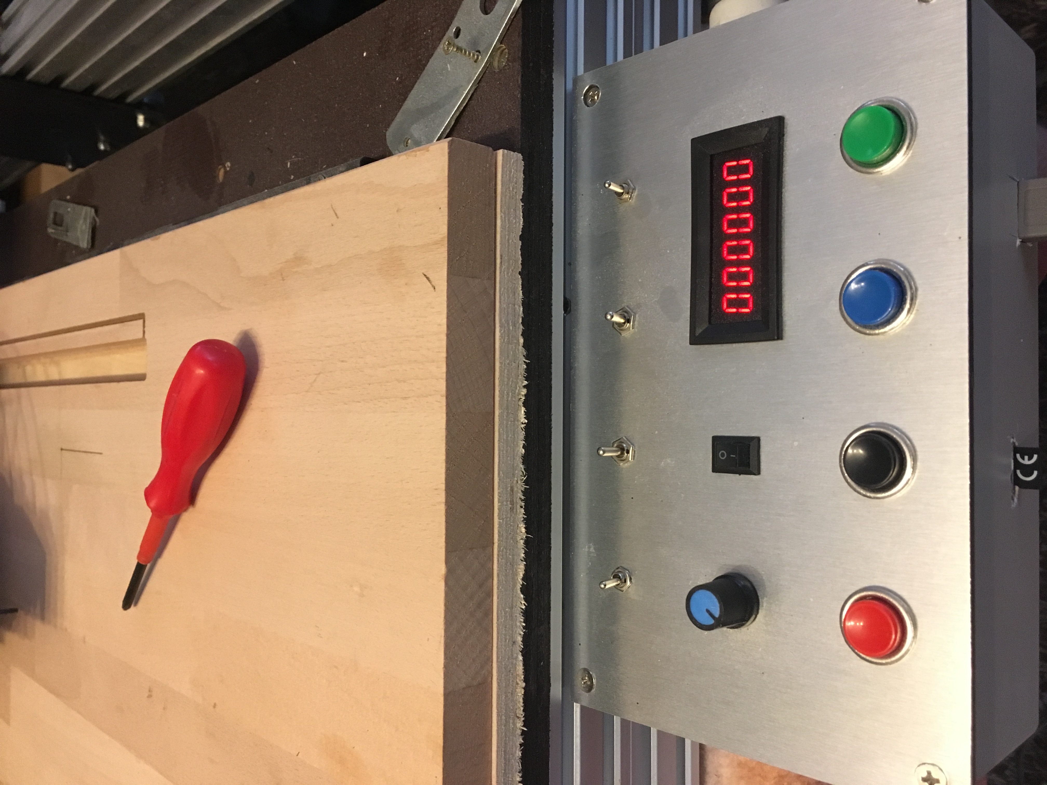
#20 – xP373Rx 于 2019-09-24
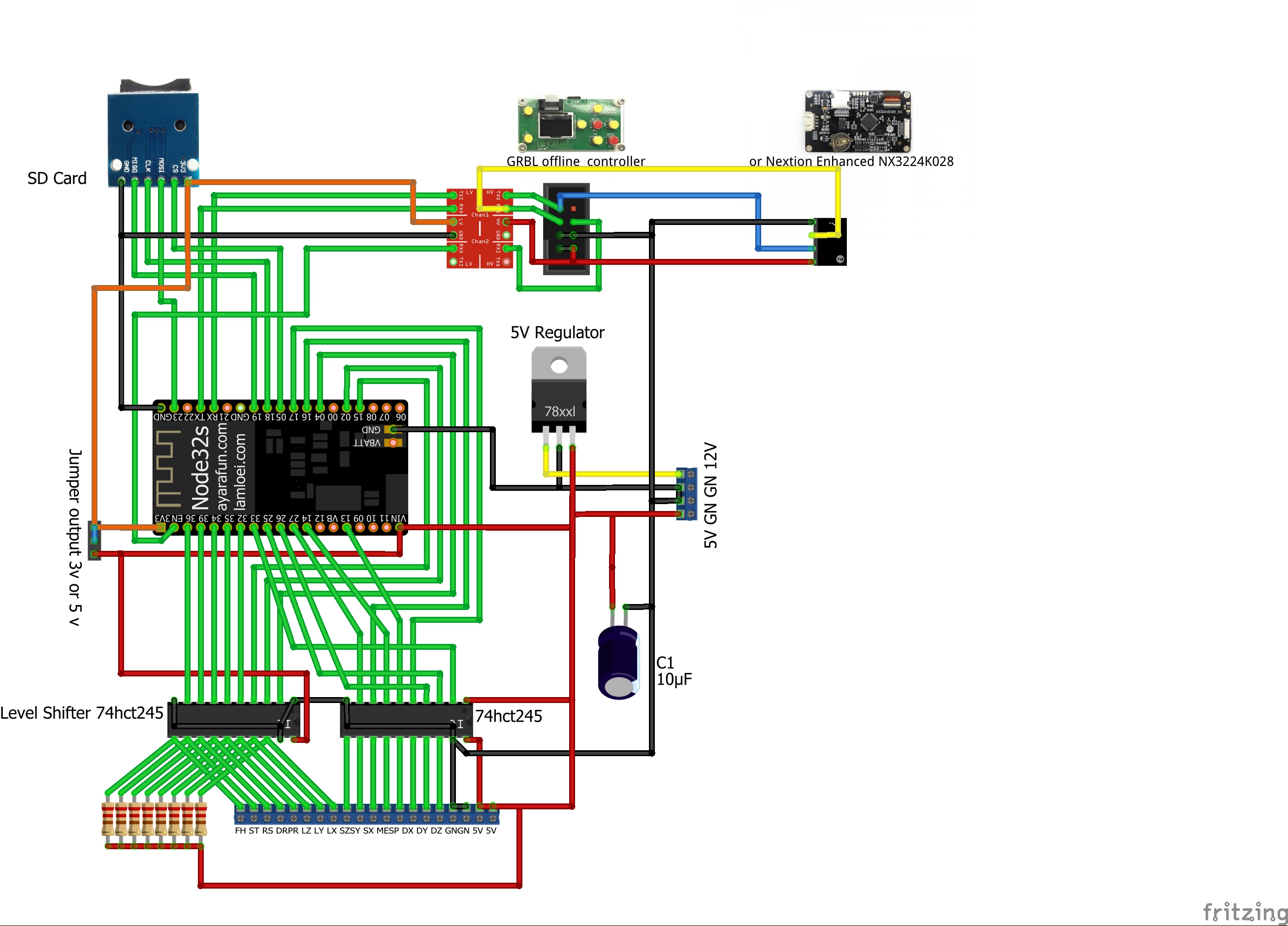
I use 2 74HCT245 to drive the optos on my stepper drivers.
http://gsgrid.net/gcode/grblesp32.jpg
http://gsgrid.net/harb/harb/PitsIphone/Alle%20Fotos/IMG_5453.JPG
http://gsgrid.net/harb/harb/PitsIphone/Alle%20Fotos/IMG_5454.JPG
Works slike a charm.
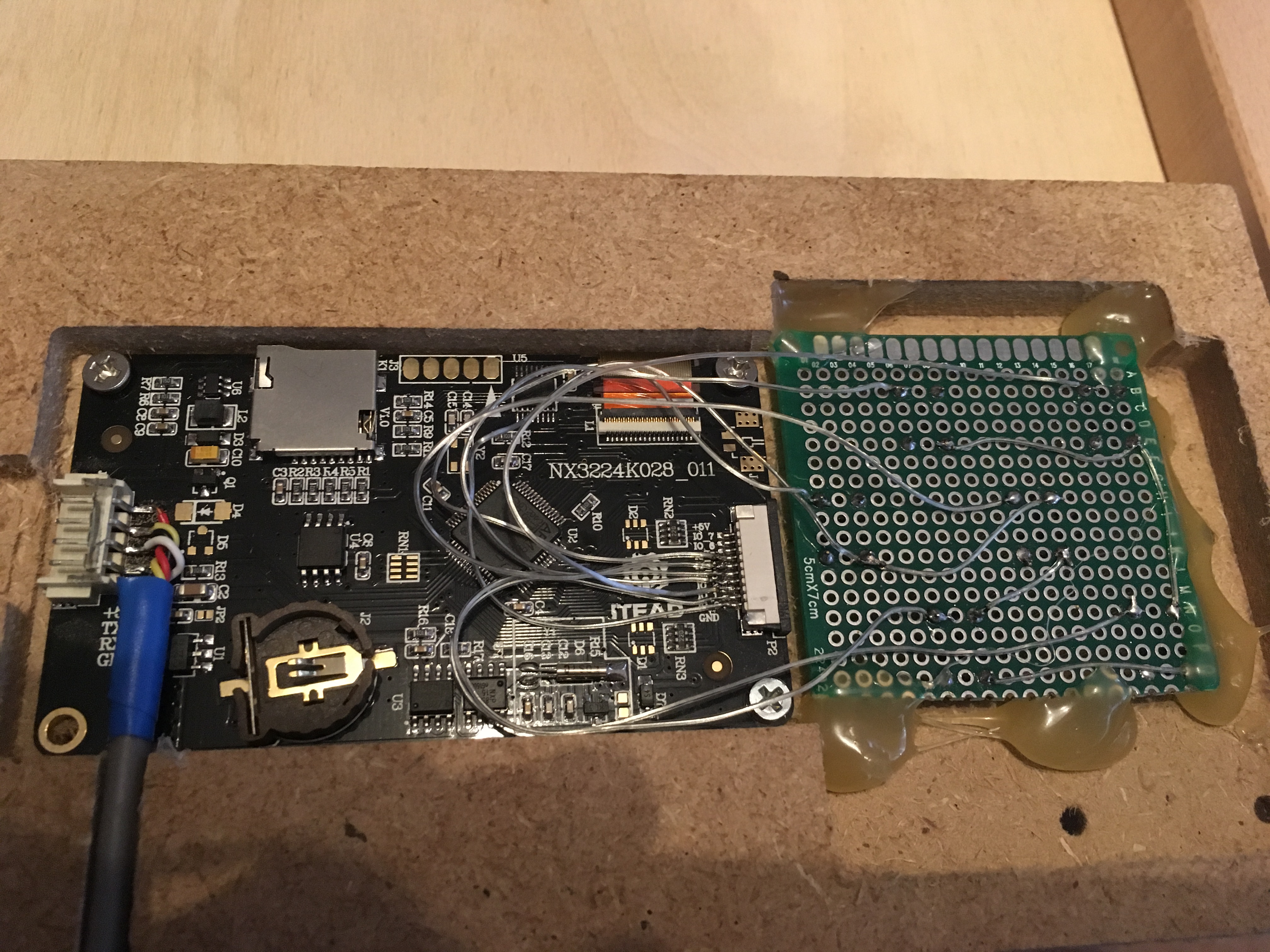
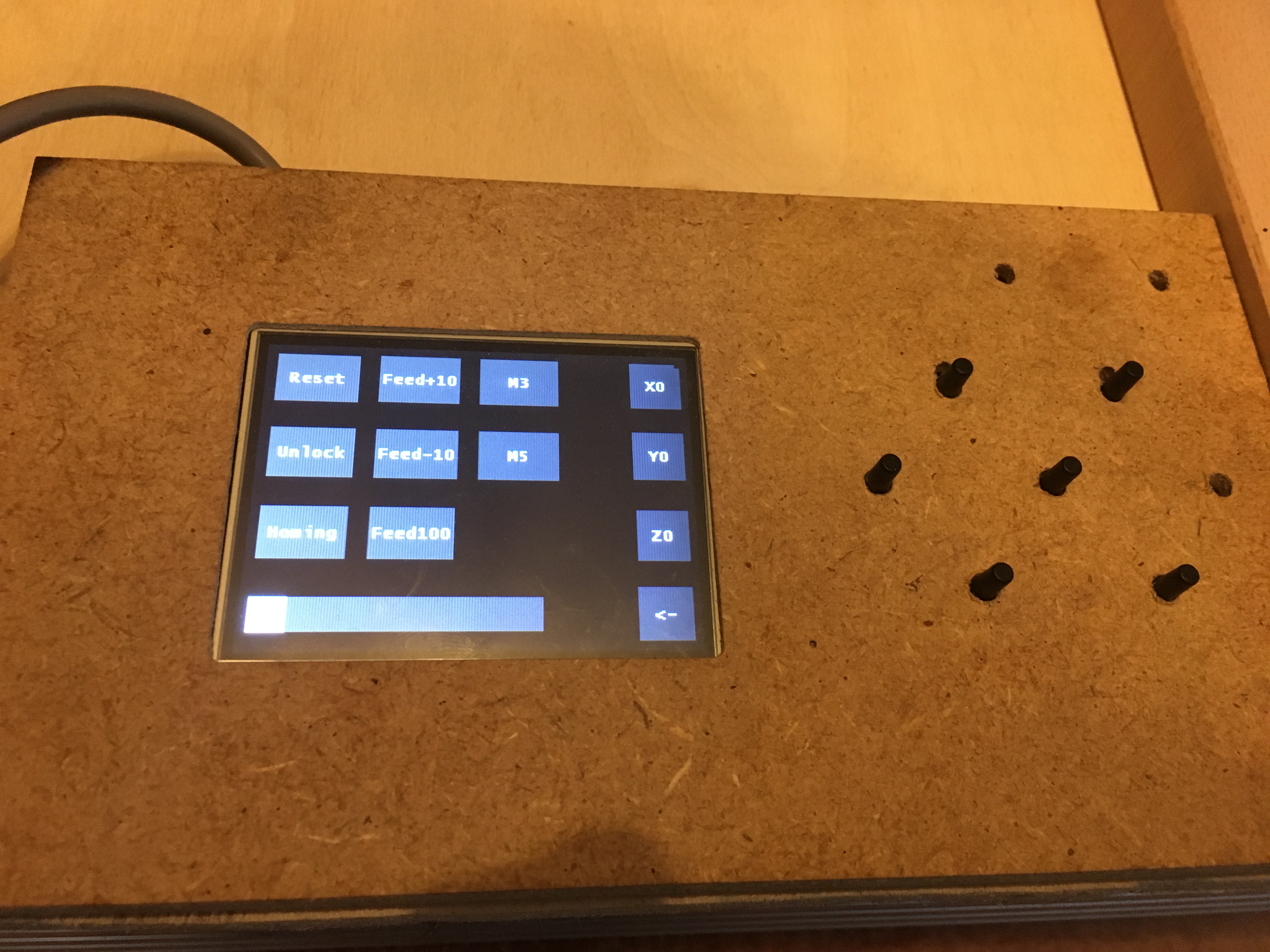
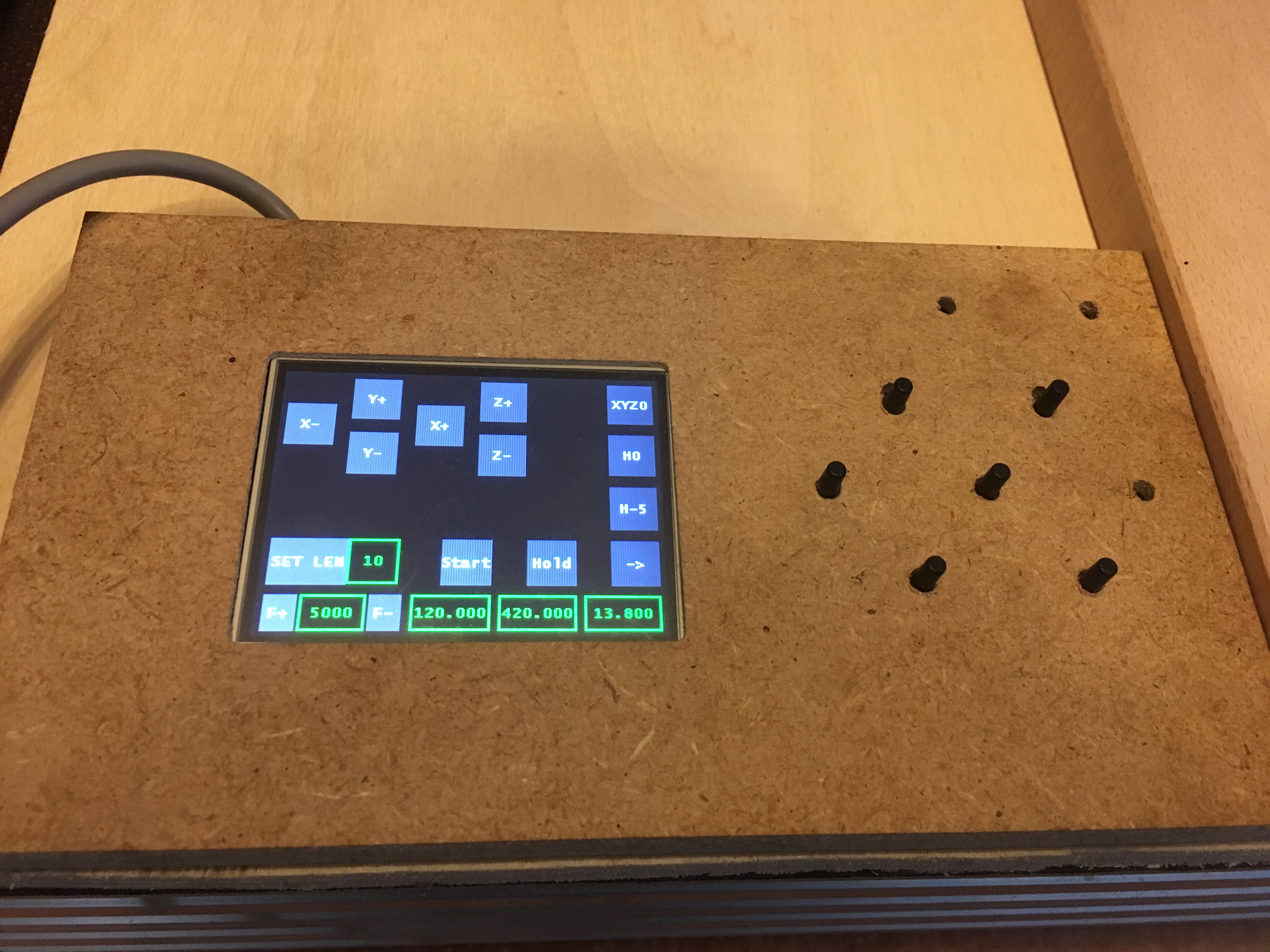
Also hacked the Nextion display to control the esp.
http://gsgrid.net/harb/harb/PitsIphone/Alle%20Fotos/IMG_5457.JPG
http://gsgrid.net/harb/harb/PitsIphone/Alle%20Fotos/IMG_5456.JPG
http://gsgrid.net/harb/harb/PitsIphone/Alle%20Fotos/IMG_5455.JPG
#21 – JackHouseLab 于 2019-09-24
Looks great ![]()
Is display connected with ESP32 via cable or wireless maybe?
My board in real:
!20190923_212057
Not conneced to machine yet, but I did some tests by oscilloscope, and everything seems good.
As I can see, ESP32 module takes more current, when it is in AP mode (140mA) than Station mode (about 70-80mA).
So I added small heatsink to 7805 IC (it looks bigger on the picture than in real ![]() )
)
I had to uncomment some lines in config files to get Hold/Resume/Abort lines working.
Now it’s time to replace old arduino grbl controller by new one, and check how it works ![]()
#22 – JamesNewton 于 2019-09-24
VERY nice looking board there Jack. Pretty much “shut up and take my money” nice. Only thing I would add is PMinMO headers for open source drivers.
http://www.massmind.org/Techref/io/PMinMO.htm
#23 – JackHouseLab 于 2019-09-24
Thanks ![]()
I connected to machine , but have problem with homing (settings are the same as original grbl has) – after about 2mm of move I have such message:
Alarm
Homing fail. Pull off travel failed to clear limit switch. Try increasing pull-off setting or check wiring.
After increasing pull-off setting to 200 (from 2), the move was continuous (for X-homing) and the limit switch didn’t worked, and only hand reset saved me from damage of machine.
Is something missing (commented out) in the compilation?
Edit:
Ok..I had to invert limit pins ($5),and now homing is working properly.
Some differences from original grbl ?
#24 – bdring 于 2019-09-25
It is good to check the limit switches manually by looking at the ? response.
#25 – misan 于 2019-09-25
LEDs on inputs and outputs may come in handy for troubleshooting.
#26 – JackHouseLab 于 2019-09-25
Now everything seems to work perfectly ![]()
I just have checked probe, and it works OK too.
Now I have to change wires and remove some of not necessary connectors, to make sure of good connections beetwen controller and rest of electronic modules, etc…
I made some changes in config files, but each time I have to remove ESP32 from socket, to flash it properly. When it is inserted in board, I cannot reprogram it (message from Arduino IDE about bad checksum after programming).
It is common or only my problem?
Fortunately enclosure have removable top lid, so I have quite good access to ESP32 ![]()
Attaching LEDs to inputs and outputs is a good idea – it would be up to 20 LEDs (with Power LEDs).
In next version of PCB I could make some changes, add connectors and even design front panel PCB with SMD LEDs for easy soldering.
#27 – AbySet 于 2019-09-26
JackHouseLab said:
“When it is inserted in board, I cannot reprogram it (message from Arduino IDE about bad checksum after programming).”
This happends when RX and TX are connected to the main board and are not (NC) whitch disturbs usb data, but i’m not sure whitch gpio they are connected to, see here:
https://github.com/eerimoq/simba/issues/137
#28 – misan 于 2019-09-26
Certain pins have to be low or high when uploading code according to the
information in here:
https://randomnerdtutorials.com/esp32-pinout-reference-gpios/
On Thu, Sep 26, 2019 at 10:34 AM AbySet
> JackHouseLab said:
> “When it is inserted in board, I cannot reprogram it (message from Arduino
> IDE about bad checksum after programming).”
>
> This happends when RX and TX are connected to the main board and are not
> (NC) whitch disturbs usb data, but i’m not sure whitch gpio they are
> connected to, see here:
> eerimoq/simba#137 <https://github.com/eerimoq/simba/issues/137>
>
> —
> You are receiving this because you were mentioned.
> Reply to this email directly, view it on GitHub
> <https://github.com/bdring/GrblEsp32/issues/171?emailsource=notifications&email_token=AADRZSHWYUAQYVXJ6LOMVL3QLRXYNA5CNFSM4H2R5Y2KYY3PNVWWK3TUL52HS4DFVREXG43VMVBW63LNMVXHJKTDN5WW2ZLOORPWSZGOD7UZCMA#issuecomment-535400752>,
> or mute the thread
> <https://github.com/notifications/unsubscribe-auth/AADRZSBFFVD5Y667E4ZTSZ3QLRXYNANCNFSM4H2R5Y2A>
> .
>
#29 – JackHouseLab 于 2019-09-30
Thanks for the links ![]()
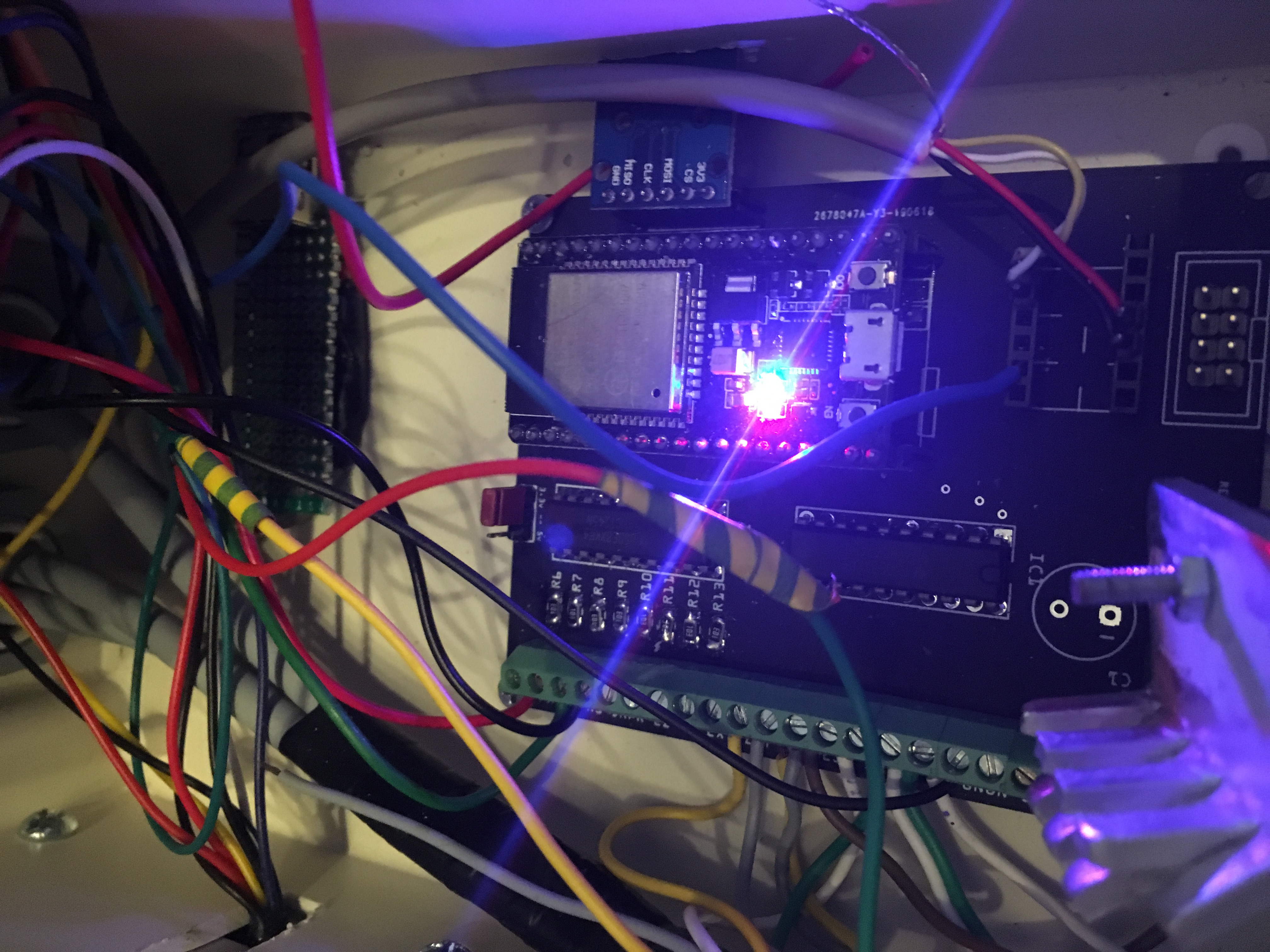
I will check which pin is making bad work, but I have to make another controller board for this, because this one is sitting in my machine:
!GRBLESP32in_machine
It works 3 times faster than original arduino based grbl CNC controller ![]()
It (probably) would be better to make Probe input as internally connected to Vdd, and switched on by shorting input (cathode of internal LED diode in optocoupler) to GND, than anode to Vdd, as is done now.
It would allow you to GND your spindle (now I can’t do this, but it works with +12V anyway).
I’m really not sure which way is better ![]()
#30 – jasinghuang 于 2019-11-07
> Thanks for the links ![]()
> I will check which pin is making bad work, but I have to make another controller board for this, because this one is sitting in my machine:
> !GRBLESP32in_machine
> It works 3 times faster than original arduino based grbl CNC controller ![]()
>
> It (probably) would be better to make Probe input as internally connected to Vdd, and switched on by shorting input (cathode of internal LED diode in optocoupler) to GND, than anode to Vdd, as is done now.
> It would allow you to GND your spindle (now I can’t do this, but it works with +12V anyway).
> I’m really not sure which way is better ![]()
Hi JackHouseLab, nice design! Would you share the design file or pcb doc? I also want to make one. Thanks
![[gnea/grbl-Mega Issue#1] $ command extentions](https://www.grblhal.com/wp-content/themes/gitphp/timthumb.php?src=https://www.grblhal.com/wp-content/themes/gitphp/assets/img/pic/4.jpg&h=110&w=185&q=90&zc=1&ct=1)
![[gnea/grbl-Mega Issue#3] ATMega16U2 virtual com port on ATMega2560](https://www.grblhal.com/wp-content/themes/gitphp/timthumb.php?src=https://www.grblhal.com/wp-content/themes/gitphp/assets/img/pic/11.jpg&h=110&w=185&q=90&zc=1&ct=1)
![[gnea/grbl-Mega Issue#4] Real-time adjustable feedrates](https://www.grblhal.com/wp-content/themes/gitphp/timthumb.php?src=https://www.grblhal.com/wp-content/themes/gitphp/assets/img/pic/7.jpg&h=110&w=185&q=90&zc=1&ct=1)
#1 – AbySet 于 2019-06-23
Great job, it is just what i was looking for.
Is it open source? if so, where can we find schematic, pcb and esp32 firmware for it ?
I would like to put this in my cnc machine as soon i get it.
Thank you.