
I made a hall effect sensor board here: https://easyeda.com/greenail/endstop5v3v_hall
I’m using the voltage drop from the LED to get the signal down to esp32 3.3v TTL range. I’m wondering if there any issues with this? I assume the biggest issue is if the led fails closed which I understand is pretty rare. The current is very low but it could still be a problem @5v. This solution It is nice because the LED also turns off when the hall sensor latches but I suppose a voltage divider works better?
I’ve been using these sensors with a level shifter but I have way too many wires already. I’d like to get the wire management under control and make a decent case with integrated cooling. If anyone knows of a good case please recommend!
Also, is there a discussion forum for more general questions like this?
评论 (7)
#2 – jschoch 于 2019-05-18
i just turn the magnet sideways. I’m using some N42 10mm magnets and have them around 15mm away from the sensor. the latching works if the right pole hits first since it unlatches on pulloff when the other poll passes. There is a condition where you might need to power cycle everything if it latches before you home which has happened once (not sure what cause dit).. it works great and the only hassle is the level shifting wire mess due to the 4.5v min for these dirt cheap us1881 sensors. I literally have it running now with just direct wires and some heat shrink to prevent shorts. My repeatability for homing has been spot on but I should test it vs a mechanical switch or a standard non-latching hall sensor to see any difference in repeatability.
#3 – jschoch 于 2019-05-22
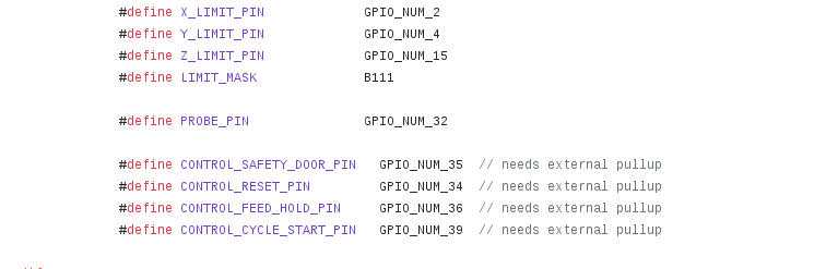
Bart, your schematic for the 2.1 board shows the RC filters and at the top it says that they don’t have internal pullups. The HOLD, Start, Reset, and Door pins show external pullups. Do the limit pins have internal pullups or no pullups at all?
Here I found way more ways to do the interface than I thought possible!
https://next-hack.com/index.php/2017/09/15/how-to-interface-a-5v-output-to-a-3-3v-input/
#4 – bdring 于 2019-05-22
Most I/O pins have optional pullup and pull down resistors. A few don’t. I have listed those on this page.
#5 – Geekoid85 于 2019-07-17
Okay so if I understand correctly I only need to add the 100nf cap on those limit switches input and I’m good to go ? (for the esp32 alone I mean, on the development board it’s already there)
!image
Because without a pull up it will be really unstable I guess the default cpu_map.h “activate” the internal pullup resistor of the esp32 ?
!image
!image
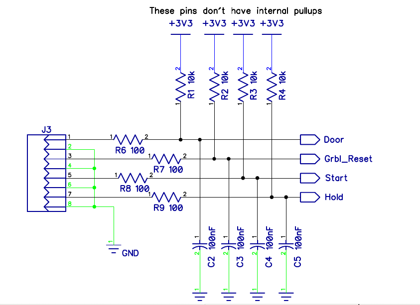
Since on your schematics and wiki those io are not marked as on the need for an external pullup like the door pin for example.
Also, I’m sure you have a good reason to but what are the 100 ohms resistors for ? I guess some sort of current limiting to protect the io, but I=3.3/100 = 33ma witch is way beyond the 12ma that the esp can deliver. I think I’m not getting something. I already see that on some arduino uno output but never on an input ! Just curious :’)
Thanks again you’re wiki and code comment are so nice, really helpfull.
#6 – Geekoid85 于 2019-07-17
Almost forgot. Using 10k on R1 R2 R3 and R4 make a difference from using 4.7k like on the grbl wiki ? Since this is not a low power device 4.7k should be more stable because it induce a bigger current right ?
https://github.com/gnea/grbl/wiki/Wiring-Limit-Switches
!image
#7 – Geekoid85 于 2019-07-18
!image
I have found the response for one of my question. Yes the internal pullup are “activated” by default on limits switches input because the pin that does not have internal pull up are ignored by default for stability reason.
![[gnea/grbl-Mega Issue#1] $ command extentions](https://www.grblhal.com/wp-content/themes/gitphp/timthumb.php?src=https://www.grblhal.com/wp-content/themes/gitphp/assets/img/pic/4.jpg&h=110&w=185&q=90&zc=1&ct=1)
![[gnea/grbl-Mega Issue#2] Better interrupt priorities](https://www.grblhal.com/wp-content/themes/gitphp/timthumb.php?src=https://www.grblhal.com/wp-content/themes/gitphp/assets/img/pic/10.jpg&h=110&w=185&q=90&zc=1&ct=1)
![[gnea/grbl-Mega Issue#4] Real-time adjustable feedrates](https://www.grblhal.com/wp-content/themes/gitphp/timthumb.php?src=https://www.grblhal.com/wp-content/themes/gitphp/assets/img/pic/7.jpg&h=110&w=185&q=90&zc=1&ct=1)
#1 – bdring 于 2019-05-17
What do you plan to use if for. The latching is interesting, but how do you deal with that?