
I am looking into adding support for TMC2130 stepper motor drivers. These drivers have a lot of cool features, but you can only access most of them via SPI.
To save I/O pins, I was wondering if it would be possible to put them on the same SPI bus as the SD card. Each SPI device would need its own CS pin, but I would not need additional MISO, MOSI pins.
Just wondering if this could be done without breaking the SD feature. Most of the SPI to the drivers is done at startup and maybe to reduce current after a job is done.
Please don’t suggest external I/O devices, that is not what THIS discussion is about.
评论 (30)
#2 – bdring 于 2019-03-25
That’s that is a good sign. I think I may try it.
#3 – cprezzi 于 2019-03-25
Just make sure that you have good shielding of the traces near the stepper drivers, as the stepper outputs may produce a lot of electrical noice.
#4 – DavidBoman 于 2019-03-26
How does the SD card SPI work today? According to the schematics (http://www.buildlog.net/blog/wp-content/uploads/2018/10/schmesp32cnctestv3p1.pdf) theCS/SCK/MOSI are connected to Spindledir/Spindelenbl/Mist…. does this mean that spindle and mist control is unusable when using the SD card?
Maybe #50 is a good candidate for getting more output ports without having to tackle the interrupt issue on input ports.
#5 – bdring 于 2019-03-26
Yes, those features are not usable when you use an SD card on that board.
#6 – DavidBoman 于 2019-03-26
Thanks – then I understand the design.
#7 – Slixxor 于 2019-03-26
Yes you can do it. you need to change the code for accessing the SPI bus though. Using the SS pin on each SPI device. here’s a great video on isolating devices on the SPI bus. https://www.youtube.com/watch?v=_p6m2WwF2Jk&t=467s
I haven’t checked if you have enough digital pins to do it though, as you need 1 pin for each SS pin on each device.
Personally, i’d look at implementing another axis that can be slaved.
#8 – bdring 于 2019-03-27
I got one working on my image
I am using this library. It works for great ESP32, but many of the examples use timers, etc registers from AVR that need to be changed to ESP32.
I am using some cheap Fysetc brand modules. I needed to modify the solder jumpers to put them in SPI mode and move some headers to the top side.
I still have a lot of learning to do about the various modes. I did see that you can daisy chain the drivers. The library does not support that though. That would save a lot of CS I/O lines.
I am currently testing with stand alone programs (Not Grbl_ESP32), so I don’t know how well it plays with the SD card.
#9 – bdring 于 2019-03-27
If an I/O expander is used, it might be nice to have one with a little extra functionality. Input interrupts as well as PWM output. The PWM would need to be able to run hobby servos with a decent resolution.
#10 – DavidBoman 于 2019-03-28
I’ve been researching I/O-expanders and usually they come in both SPI and I2C-flavours. Which one do you think would be beneficial? If we already use SPI it would only add one additional pin for CS – on the other hand – it might conflict with the SD card reader from a utilization stand point. I2C is nice but what about the I2C-pins on the card today (GPIO21/22?) are they used for something else or could we them for an expander?
#11 – bdring 于 2019-03-28
I could probably work with either type. Yet another SPI might be asking for problems though. I might try using a very small FPGA as an I2C slave device. It would add a lot of flexibility.
Servo PWM is a challenge for many existing devices. You are dealing with a 1ms range in a 50Hz cycle. That means you essentially can only use 1/20th of the resolution. A 12 bit PWM yields less than 8 bits of range. I think I would want at least 16 bits like the ESP32 provides.
#12 – Slixxor 于 2019-03-28
I2C is way too slow. SPI would be a much better option.
#13 – bdring 于 2019-03-29
Hopefully speed is not an issue, but I’ll see if SPI will better.
#14 – Slixxor 于 2019-03-29
@bdring
Check out some good info here. https://www.lifewire.com/selecting-between-i2c-and-spi-819003
We prefer SPI over I2C for fast comms. Although, I2C certainly has it’s place. i.e: With 2-4 line LCD displays. They can easily be updated via the I2C library. You can also run very long cable runs on the I2C bus. i.e: connecting multiple sensors together in a round robbin.
I know you’re pretty savvy already Bart, you’ll make the right choice ![]()
#15 – cprezzi 于 2019-03-29
@Slixxor I don’t see a problem with speed. Configuration of the stepper drivers during machine bootup doesn’t need to be very fast. I2C would be totaly fine.
Many boards like Smoothieboard, MKS-SBase, Cohesion3D and others are allredy using I2C for stepper current configuration. No problem with that.
#16 – Slixxor 于 2019-03-29
@cprezzi ok, go with I2C then ![]()
#17 – misan 于 2019-03-29
Polling for potential missing steps might need to be done more often.
#18 – Slixxor 于 2019-03-29
@misan
I didn’t bother saying it. Imagine a 1500x1500mm machine with a large half sheet work piece on it. I can only imagine where the zero will end up by the end of the job ![]()
#19 – bdring 于 2019-04-01
…more testing.
I am able to run a TMC2130 stepper in Grbl_ESP32 now. I am only initializing the drivers right now, but the SD Card on the same SPI bus works fine.
Here are the things I am setting now. I like being able to set the hold current. That reduces the current after a selectable amount the movement has stopped. Here is my init right now.
TMC2130.microsteps(32);
TMC2130.SilentStepStick2130(600); // Set stepper current to 600mA
TMC2130.stealthChop(1); // Enable extremely quiet stepping
TMC2130.irun(31); // 100% = 31
TMC2130.ihold(4); // 100% = 31
TMC2130.TPOWERDOWN(1);
TMC2130.iholddelay(1); // hold delay approx 1 sec = val/4
#20 – DavidBoman 于 2019-04-01
@bdring : Can you elaborate on this comment: https://github.com/bdring/Grbl_Esp32/issues/108#issuecomment-477572206?
> Servo PWM is a challenge for many existing devices. You are dealing with a 1ms range in a 50Hz cycle. That means you essentially can only use 1/20th of the resolution. A 12 bit PWM yields less than 8 bits of range. I think I would want at least 16 bits like the ESP32 provides.
I’m not sure I’m following the 1/20 corresponding to 8 bits effective resolution-thought. From what I understand these PWM-circuits often have an internal clock. Take the PCA9585 (https://www.mouser.se/datasheet/2/302/PCA9685-1127478.pdf) poularized by Adfruit on their breakout board (https://www.adafruit.com/product/815) for example…. According to Adafruits description it has “12-bit resolution for each output – for servos, that means about 4us resolution at 60Hz update rate”. Am I missing something that makes this chip a bad candidate for a servo driver?
#21 – bdring 于 2019-04-01
I am not exactly sure how that device works, but here is the problem with generic PWMs and servos.
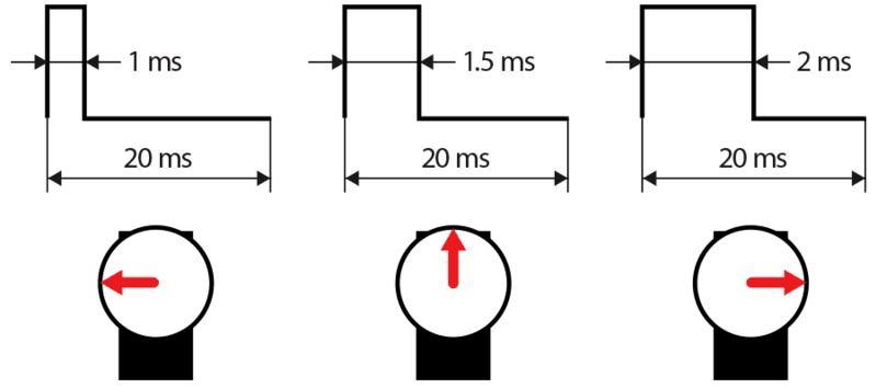
The signal spends most of the time in the LOW state at any point in the travel (image is not to scale). The PWM resolution covers that whole cycle, so much of the resolution is wasted.
The basic end points of a servo are 1ms and 2ms. That means 1ms is the range. In your example 1ms / 4us is only 250. That is less than 8 bit.
#22 – DavidBoman 于 2019-04-02
Alright, now I follow your reasoning. But the the question is: Do wee need to support 20ms cycles? According to Wikipedia on servos that seems to come from historical reasons and most of the servos of today can handle much higher frequencies – the important thing is the 1-2ms on the high pulses. This is what Wikipedia says on servos (https://en.wikipedia.org/wiki/Servo_control):
> Modern RC servo position is not defined by the PWM duty cycle (i.e., ON vs OFF time) but only by the width of the pulse. (This is different from the PWM used, for example, in some DC motor speed control). Most RC servos move to the same position when they receive a 1.5 ms pulse every 6 ms (a duty cycle of 25%) as when they receive a 1.5 ms pulse every 25 ms (a duty cycle of 6%) – in both cases, they turn to the central position (neutral position). With many RC servos, as long as the refresh rate (how many times per second the pulse is sent, aka the pulse repetition rate) is in a range of 40 Hz to 200 Hz, the exact value of the refresh rate is irrelevant.
So running with a 200Hz refresh rate would give a cycle time of 5ms. 1.5ms of 5ms is 1/3 of the resolution which is 10-11 effective bits. 10 bits resolution should correspond to 0.18 degrees per bit. But I read somewhere that a standard servo have a deadband (https://en.wikipedia.org/wiki/Deadband) of ~0.4 degrees so anything lower than that would not give any effect anyway (using that calculation backward would give 180/0.4 = 450 =~ 512 = 2^9. So the maximum “needed” effective resolution would be 9 bits).
… all with the reservation that my math can be completely off at this time of the day ![]()
#23 – bdring 于 2019-04-02
Most of the cheap servos I use are not “modern” or digital. They are analog. Analog servos compare the signal pulse to the internal pulse created by the position of the potentiometer connected to the shaft. The comparison creates an analog error signal proportional to the position error. This error is amplified and fed directly to the motor. This creates pulses of power to the motor. You can feel these pulses by trying to move the motor out of position. You can feel the pulse rate. The strength is proportional to the displacement. I have found if you speed up the signal frequency, the motors will run very hot and eventually fail.
With this said, getting 8 bits of resolution out of an analog servo is tough. The deadband is typically 4us – 8us. The deadband is used to prevent the servo from “hunting” and draining the battery.
Digital or “modern” servos don’t care about the rate. They use the pulse to set a target and a separate PID process moves it. If you displace a digital servo, it will feel quite different and strongly oppose a small displacement. The deadband can often be programmed to a low rate or even eliminated on some. Many servos claim a 10 bit resolution. That is probably the ADC resolution on the pot though.
12-bits is probably OK if you allow the user to adjust the duty cycle. You run the risk of a newbie burning up an analog servo though.
#24 – bdring 于 2019-04-11
Update: Earlier this week I received a custom PCB to do further testing. This uses (2) TMC2130 drivers in SPI mode on the same bus as the SD card. I hope to have it assembled tomorrow.
I can use it to make a silent pen plotter.
#25 – Slixxor 于 2019-04-11
I’m glad you opted for SPI, enjoy!
#26 – povi2946 于 2019-05-07
My 2x TMC2130 are already waiting for this board!
#27 – bdring 于 2019-05-07
The boards appears to work great. I have a few extra, I would happy to sell to help support this project. They would be $40 each. Fully assembled, but no modules installed.
I can write up a quick note on how to use them and help via Slack if needed.
#28 – povi2946 于 2019-05-08
Great. Let me know how should I contact you.
#30 – bdring 于 2019-05-08
There is now a GitHub repo for my https://github.com/bdring/Grbl_Esp32/issues/108
-
![[gnea/grbl-Mega Issue#1] $ command extentions](https://www.grblhal.com/wp-content/themes/gitphp/timthumb.php?src=https://www.grblhal.com/wp-content/themes/gitphp/assets/img/pic/12.jpg&h=110&w=185&q=90&zc=1&ct=1)
[gnea/grbl-Mega Issue#1] $ command extentions -
![[gnea/grbl-Mega Issue#2] Better interrupt priorities](https://www.grblhal.com/wp-content/themes/gitphp/timthumb.php?src=https://www.grblhal.com/wp-content/themes/gitphp/assets/img/pic/1.jpg&h=110&w=185&q=90&zc=1&ct=1)
[gnea/grbl-Mega Issue#2] Better interrupt priorities -
[gnea/grbl-Mega Issue#3] ATMega16U2 virtual com port on ATMega2560 -
![[gnea/grbl-Mega Issue#4] Real-time adjustable feedrates](https://www.grblhal.com/wp-content/themes/gitphp/timthumb.php?src=https://www.grblhal.com/wp-content/themes/gitphp/assets/img/pic/3.jpg&h=110&w=185&q=90&zc=1&ct=1)
[gnea/grbl-Mega Issue#4] Real-time adjustable feedrates
- [gnea/grbl-Mega Issue#1] $ command extentions
- [gnea/grbl-Mega Issue#2] Better interrupt priorities
- [gnea/grbl-Mega Issue#3] ATMega16U2 virtual com port on ATMega2560
- [gnea/grbl-Mega Issue#4] Real-time adjustable feedrates
- [gnea/grbl-Mega Issue#5] question about the download zip contents
- [gnea/grbl-Mega Issue#6] Adding outputs for external state signals
- [gnea/grbl-Mega Issue#7] which g-code sender is being used in grbl-Mega testing?
- [gnea/grbl-Mega Issue#8] Frecuencia y velocidad de avance.
#1 – luc-github 于 2019-03-25
I do not know if this answer your question but this screen http://www.panucatt.com/product_p/vikilcd2.htm
share LCD Miso/Mosi/SCK SPI pins with SD card ones
So I think should be possible to use same SPI for TMC too