
hi, I used GRBL.1.1f to run my mil CNC, every things work fine unless M5 command trigger the hard limit alarm as following whereas not hard limit trigger , M3 & M4 just work fine
“
> M3

< ok
> M5

< ok
< ALARM:1 	Hard limit triggered.Machine position is likely lost due to sudden and immediate halt.Re - homing is highly recommended.
< [MSG:Reset to continue]
> M3
`
GRBL setting
`
< $0=10 	(Step pulse time, microseconds)
< $1=255 	(Step idle delay, milliseconds)
< $2=0 	(Step pulse invert, mask)
< $3=7 	(Step direction invert, mask)
< $4=1 	(Invert step enable pin, boolean)
< $5=0 	(Invert limit pins, boolean)
< $6=0 	(Invert probe pin, boolean)
< $10=1 	(Status report options, mask)
< $11=0.010 	(Junction deviation, millimeters)
< $12=0.002 	(Arc tolerance, millimeters)
< $13=0 	(Report in inches, boolean)
< $20=0 	(Soft limits enable, boolean)
< $21=1 	(Hard limits enable, boolean)
< $22=1 	(Homing cycle enable, boolean)
< $23=7 	(Homing direction invert, mask)
< $24=250.000 	(Homing locate feed rate, mm/min)
< $25=100.000 	(Homing search seek rate, mm/min)
< $26=250 	(Homing switch debounce delay, milliseconds)
< $27=1.000 	(Homing switch pull-off distance, millimeters)
< $30=1000 	(Maximum spindle speed, RPM)
< $31=0 	(Minimum spindle speed, RPM)
< $32=0 	(Laser -mode enable, boolean)
< $100=83.330 	(X -axis steps per millimeter)
< $101=83.330 	(Y -axis steps per millimeter)
< $102=83.330 	(Z -axis steps per millimeter)
< $110=600.000 	(X -axis maximum rate, mm/min)
< $111=600.000 	(Y -axis maximum rate, mm/min)
< $112=600.000 	(Z -axis maximum rate, mm/min)
< $120=100.000 	(X -axis acceleration, mm/sec^2)
< $121=100.000 	(Y -axis acceleration, mm/sec^2)
< $122=100.000 	(Z -axis acceleration, mm/sec^2)
< $130=800.000 	(X -axis maximum travel, millimeters)
< $131=700.000 	(Y -axis maximum travel, millimeters)
< $132=50.000 	(Z -axis maximum travel, millimeters)
< ok
评论 (23)
#2 - mkeyno 于 2017-06-18
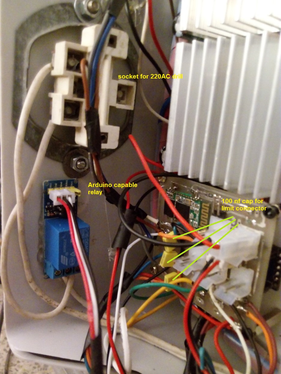
I used the Arduino capable opto coupler to drive 220 AC drail and 100 nf cap for imitators as following image , @electrokean can you tell me which part could causing EMI ?
!20170618_095515
!20170618_095454
!20170618_095525
#3 - 109JB 于 2017-06-18
are any of your wires shielded? None appear to be.
#4 - mkeyno 于 2017-06-18
I have no idea where should be shield because I ran couple of CNC with GRBL & CNC with no such EMF effects , but I think it should lay on the Arduino relay because when AC 220 drill not connected it works fine , I was wonder how this relay could only affects the limiters! maybe 100 nf ceramic capacitor is not good choose for limiters
#5 - langwadt 于 2017-06-18
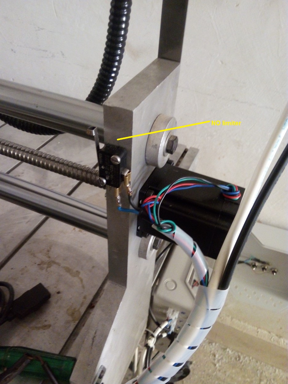
it is obviously noise coupling into the limit wires. Try changing to to NC instead of NO, should be as simple as moving a wire on the switches and changing the setting
#6 - electrokean 于 2017-06-19
@mkeyno Wow! Looking at that photo, no wonder you have issues...
The problem is going to be arcing in the relay when it turns off, due to the inductance of the spindle motor. This could possibly be reduced by adding a snubber circuit, but I'm not going to recommend trying that as mains voltage circuits should only be done by experienced people. Of course I can't stop you googling "relay snubber circuit".
Even with NC limit switches, the arcing of the relay is likely to still disrupt the arduino or BT module when they're that close and unprotected.
You need to move all the low voltage circuits away from the mains power and higher voltage parts. Ideally it should be in its own grounded metal box (maybe with a hole for the BT antenna, but away from the mains stuff). Any low voltage cabling from the Arduino (limits & stepper controls) that goes near noisy cables (i.e. AC spindle & stepper power/drive) needs to be shielded. I usually shield my stepper motor cables too, but only at the driver end.
Take a look at the electronics of the typical Chinese router/engraver machines - even they are better shielded, let alone neater and safer that yours appears to be.
#7 - mkeyno 于 2017-06-19
thanks @electrokean , actually I did some modification but not very reliable , I was wonder how my RC filter can't block the noise with different capacitor but any way I'm done with relay , I'll redesigned PCB with triac , it is so reliable and less problematic
#8 - electrokean 于 2017-06-19
@mkeyno yes, an SSR based on triac (with snubber) will be much better. You might still want to add some ferrites and shielding to improve immunity from noise. I'm sure if you remove the capacitors from the limit inputs you will find they are doing their job (especially with the unshielded limit cable running alongside the stepper cables). They just won't be able to handle all the different sources of noise coupling.
#9 - vMeph 于 2017-06-19
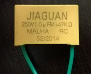
@electrokean i assume this component would be a RC filter, would something like this work?
#10 - electrokean 于 2017-06-19
@vMeph Yes, that would be an RC "snubber" - typically used with a triac when switching inductive loads, but can also be used with a relay or other mechanical switch to suppress EMI
See https://en.wikipedia.org/wiki/Snubber
#11 - vMeph 于 2017-06-19
@electrokean
i sometimes have some noise on my lines that triggers the ALARM, but is only sometimes is very rare, i notice is when the relay is turn off
im using 1-Channel H/L Level Triger Optocoupler Relay
now im wonder i could add that RC snubber betwen NO and C of the relay? to see if there is improvements, just wondering about the RC snubber value ohms and uF in that pic if would it be ok, im runing a 130W dremel.
sense the circuit will be only to turn on and off, other option could be make a circuit using like a MOC3061 Zero-Cross Optoisolator with Transistor BTA16 triac and RC snubber
#12 - electrokean 于 2017-06-21
@vMeph those particular values (1uF & 47k) seem to be for a specific application. They're very different to what I'm used to (e.g. 10nF & a few hundred ohms) but this isn't my specific area of expertise. I don't think it will hurt to try it. The zero crossing opto isolator may also help.
See https://electronics.stackexchange.com/questions/42131/how-to-design-an-rc-snubber-for-a-solenoid-relay-driving-an-inductive-load for some useful info on RC snubbers in this type of application
#13 - mkeyno 于 2017-06-21
thanks @electrokean its works much better but I'm still wonder how removing the cap, enhanced the performance , I'm not elec. eng. but I was presumed RC is always harmless , can you send couple of links that shows how good wring should be in CNC machine
#14 - jcassago 于 2017-10-10
Hi guys, I'm stuck here. Could you describe a DETAILED simple filter (for a dumb) to solve "ALARM: Hard limit (Reset to continue)". I have a mil CNC and this happens when I turn on my spindle. If I turn off hard limit ($21=0) it doesn't happen anymore but the machine gets no protection against crash and may destroy itself. Thank you.
#15 - vMeph 于 2017-10-10
Sounds like when you turn on and off relay you have EMF, relays produces arcs, i use to have that problem, one way to fix might be with a snubber filter circuit, using triac an optocoupler, at least that fix my problem, it would be also a good idea have shielded cables
#16 - jcassago 于 2017-10-10
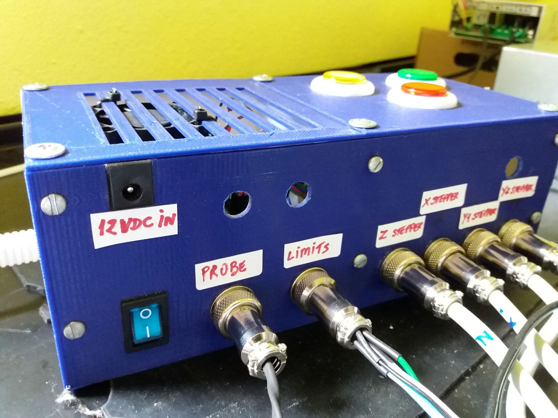
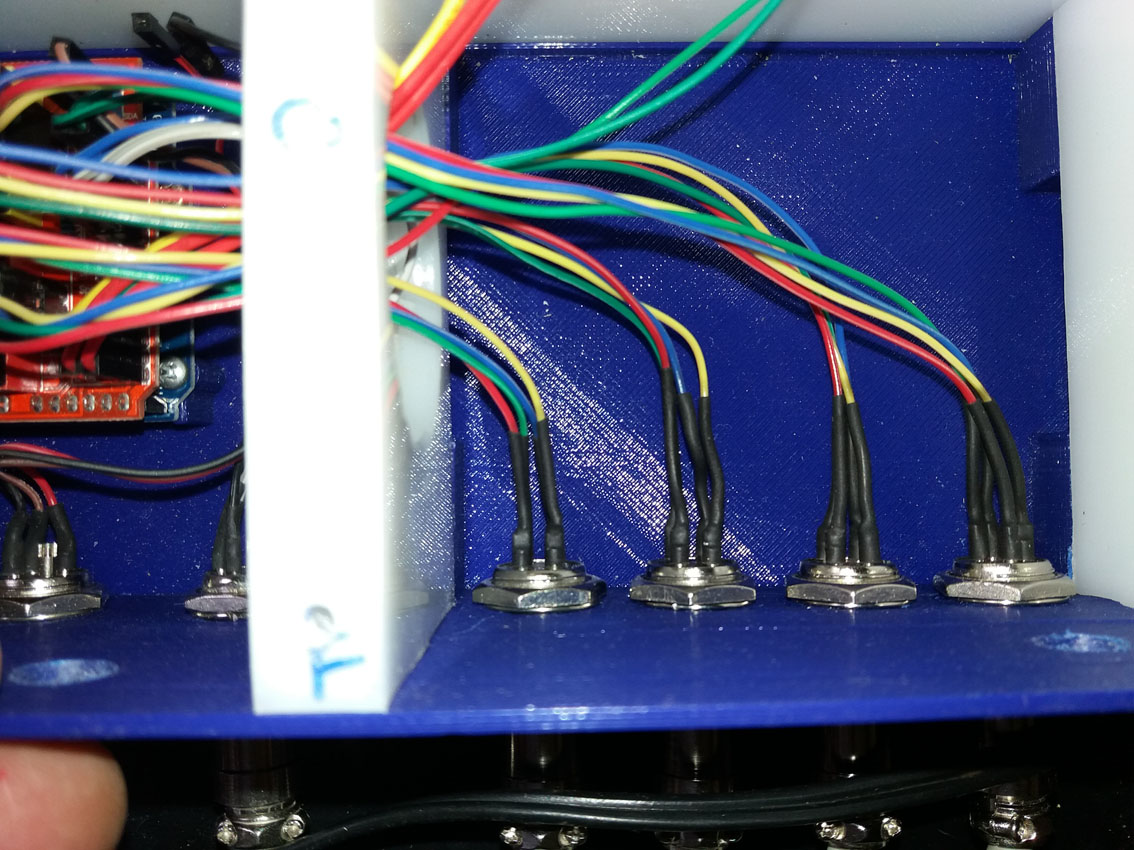
@vMeph , you're absolutely right, that's what everyone is saying. As I know almost NOTHING about electronics, I have no idea on how to CREATE a filter circuit, but I'll be able to reproduce whatever you teach me, if you could. Would you DETAIL how to make it (and I really mean detail) with all the words, and PARTS SPECS, and where to connect them all? Down here in Brasil I couldn't get these info so far. I'm using an Arduino Uno and a CNC shield controlling a mil CNC that I built myself thanks to a series of videos on youtube. Pictures of my control pannel attached. THANKS A LOT FOR YOUR HELP.
!01 general view
!02 pannel front
!03 cnc shield connections 1
!04 cnc shield connections 2
!05 steppers connections
#17 - vMeph 于 2017-10-10
Just one question what grbl version you using?
That cnc shield v3?
Did you make any changes to the shield?
#18 - jcassago 于 2017-10-10
@vMeph :
1-grbl 0.9j
2-Yes, V3
3-No changes apart setting grbl to swap between Z limit and Spindle Enable (all these are working fine, including homing)
THANKS FOR YOUR ATTENTION!!!!
#19 - vMeph 于 2017-10-10
Ok just wanted make sure you have swaped the pins
#20 - vMeph 于 2017-10-10
by the way nice looking machine you got there, bem fixe!!!
some shielded cables with proper grounds could get rid of the noises on lines also
when it comes into dealing with main voltages 230V, i would like not to be the one to give you advise, sense you got know what you doing, but most like you will just look arround and try to figuer how to do it
i used a circuit like these
!snub
you can find more detail in how it works on
http://www.bristolwatch.com/ele/triacs2.htm
dont you have any friend that understands about circuits, that maybe could give you a hand?
#21 - jcassago 于 2017-10-11
@vMeph , thank you for the tips. I'll get someone to read that circuit for me.
#22 - MitchelloCh 于 2018-11-13
hello, please...i need diagram probe v shild... thanks
#23 - Rob2029 于 2018-11-14
The diagram to connect the probe to the CNC shield? You connect a terminal
to the A5 pin and other to the ground
El nov. 12, 2018 8:17 PM, "MitchelloCh"
> hello, please...i need diagram probe v shild... thanks
>
> —
> You are receiving this because you are subscribed to this thread.
> Reply to this email directly, view it on GitHub
> <https://github.com/grbl/grbl/issues/1250#issuecomment-438103760>, or mute
> the thread
> <https://github.com/notifications/unsubscribe-auth/AjgDbXIzK9BQNFmDpATWTXhgaXhusRCjks5uuisEgaJpZM4N9KPc>
> .
>
![[gnea/grbl-Mega Issue#1] $ command extentions](https://www.grblhal.com/wp-content/themes/gitphp/timthumb.php?src=https://www.grblhal.com/wp-content/themes/gitphp/assets/img/pic/11.jpg&h=110&w=185&q=90&zc=1&ct=1)
![[gnea/grbl-Mega Issue#2] Better interrupt priorities](https://www.grblhal.com/wp-content/themes/gitphp/timthumb.php?src=https://www.grblhal.com/wp-content/themes/gitphp/assets/img/pic/10.jpg&h=110&w=185&q=90&zc=1&ct=1)
![[gnea/grbl-Mega Issue#3] ATMega16U2 virtual com port on ATMega2560](https://www.grblhal.com/wp-content/themes/gitphp/timthumb.php?src=https://www.grblhal.com/wp-content/themes/gitphp/assets/img/pic/9.jpg&h=110&w=185&q=90&zc=1&ct=1)
![[gnea/grbl-Mega Issue#4] Real-time adjustable feedrates](https://www.grblhal.com/wp-content/themes/gitphp/timthumb.php?src=https://www.grblhal.com/wp-content/themes/gitphp/assets/img/pic/8.jpg&h=110&w=185&q=90&zc=1&ct=1)
#1 - electrokean 于 2017-06-18
So it sounds like turning off your spindle is causing EMI which triggers your limit switches.
What filtering do you have on your limit inputs? Do you use shielded cables, ferrites, etc?